EasyManuals Logo

Danfoss vlt aqua Operating Instructions

Danfoss vlt aqua
182 pages
To Next Page IconTo Next Page
To Previous Page IconTo Previous Page
Page #38 background imageLoading...
Page #38 background image
Frame size F17
2232,5
(87.9)
2298,5
(90.5)
2831,5
(111.5)
2899,0
(114.1)
3632,0
(143.0)
533,0
(21.0)
599,0
(23.6)
1032,0
(40.6)
1099,5
(43.3)
32,3
(1.3)
33,3
(1.3)
535,0
(21.1)
2X 216,5
(8.5)
2X 281,3
(11.1)
35,8
(1.4)
1
2
2X
460,0
(18.1)
2336,1
(92.0)
663,5
(26.1)
305,0
(12.0)
2969,5
(116.9)
1157,2
(45.6)
994,3
(39.1)
593,0
(23.3)
130BB430.10
3X 258,5
(10.2)
3X 199,5
(7.9)
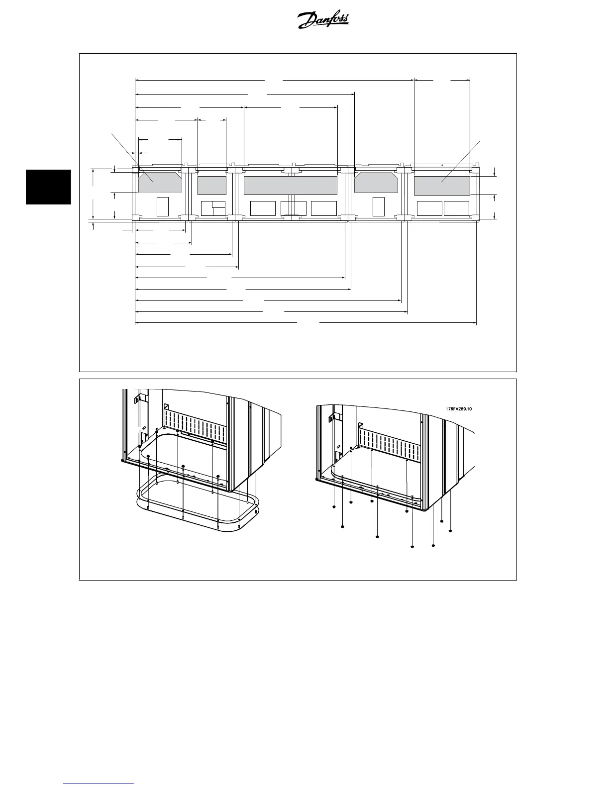
F17: Cable entries viewed from the bottom of the frequency converter
1) Mains cable connection
2) Motor cable connection
Illustration 4.25: Mounting of bottom plate, E7
The bottom plate of the E frame can be mounted from either in- or outside of the enclosure, allowing flexibility in the installation process, i.e. if mounted
from the bottom the glands and cables can be mounted before the frequency converter is placed on the pedestal.
4 How to Install
VLT AQUA Low Harmonic Drive Operating In-
structions
38 MG.20.T1.02 - VLT
®
is a registered Danfoss trademark
4

Table of Contents

Other manuals for Danfoss vlt aqua

Questions and Answers:

Question and Answer IconNeed help?

Do you have a question about the Danfoss vlt aqua and is the answer not in the manual?

Danfoss vlt aqua Specifications

General IconGeneral
Supply Voltage200-240V, 380-500V, 525-600V
EnclosureIP20
FeaturesEnergy optimization
ApprovalsCE, UL, cUL
Input Voltage Range200-240V, 380-500V, 525-600V
Output Voltage Range0 to supply voltage
Protection FeaturesOvervoltage, Undervoltage, Overcurrent, Short circuit, Ground fault
Communication InterfacesPROFIBUS
Cooling MethodAir-cooled

Related product manuals