EasyManuals Logo

Danfoss vlt aqua Operating Instructions

Danfoss vlt aqua
182 pages
To Next Page IconTo Next Page
To Previous Page IconTo Previous Page
Page #39 background imageLoading...
Page #39 background image
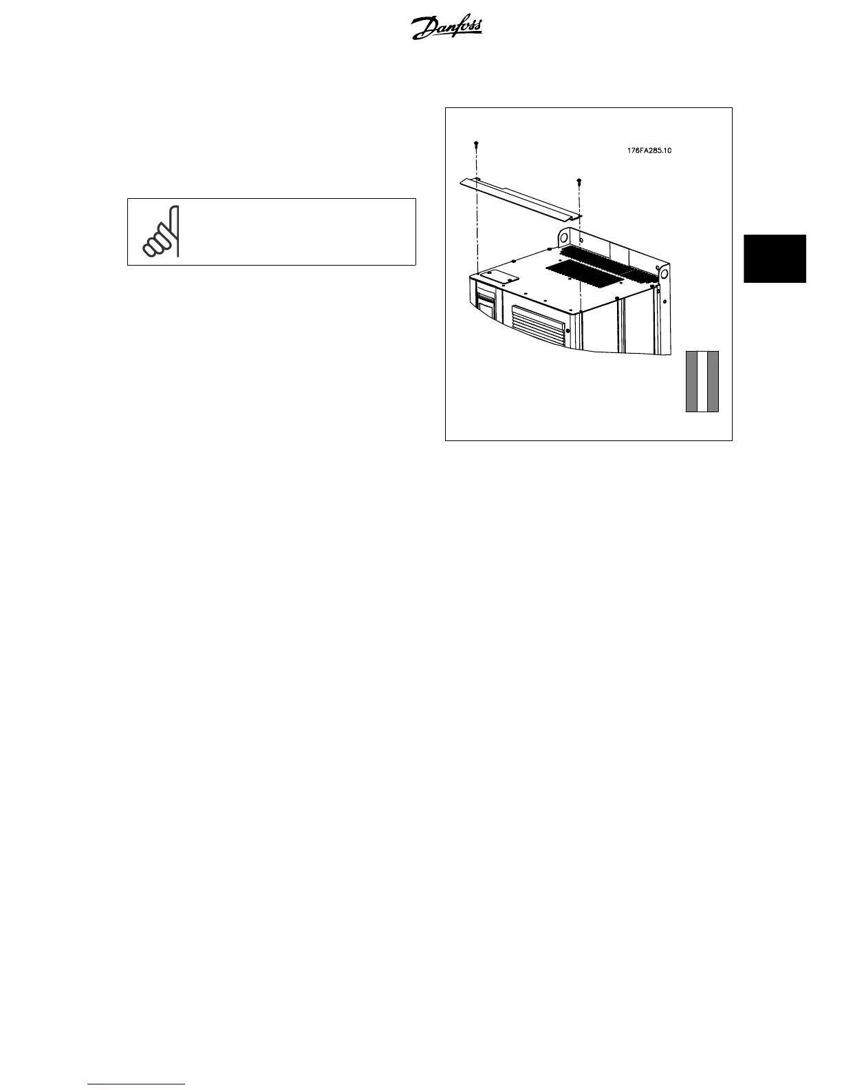
4.3.10 IP21 Drip Shield Installation (Frame size D)
To comply with the IP21 rating, a separate drip shield is to be
installed as explained below:
Remove the two front screws
Insert the drip shield and replace screws
Torque the screws to 5,6 Nm (50 in-lbs)
NB!
Drip shield is necessary on both filter and drive section.
Illustration 4.26: Drip shield installation.
VLT AQUA Low Harmonic Drive Operating In-
structions 4 How to Install
MG.20.T1.02 - VLT
®
is a registered Danfoss trademark 39
4

Table of Contents

Other manuals for Danfoss vlt aqua

Questions and Answers:

Question and Answer IconNeed help?

Do you have a question about the Danfoss vlt aqua and is the answer not in the manual?

Danfoss vlt aqua Specifications

General IconGeneral
Supply Voltage200-240V, 380-500V, 525-600V
EnclosureIP20
FeaturesEnergy optimization
ApprovalsCE, UL, cUL
Input Voltage Range200-240V, 380-500V, 525-600V
Output Voltage Range0 to supply voltage
Protection FeaturesOvervoltage, Undervoltage, Overcurrent, Short circuit, Ground fault
Communication InterfacesPROFIBUS
Cooling MethodAir-cooled

Related product manuals