3.1.2 IEEE519 Compliance
Low harmonic drives are designed to draw an ideal sinusoidal current waveform from the supply grid with a power factor of 1. Where traditional non-
linear load draws pulse-shaped currents, the low harmonic drive compensates for this via the parallel filter path which lowers the stress on the supply
grid. The low harmonic drive meets the toughest harmonic standards and has a THiD of less then 5% at full load for <3% pre-distortion on a balanced
three-phased grid. The unit is designed to meet IEEE519 recommendations for Isc/Il >20 for both uneven and even individual harmonic levels. The filter
portion of a low harmonic drive has a progressive switching frequency which leads to a wide frequency spreads producing lower individual harmonic levels
above the 50th.
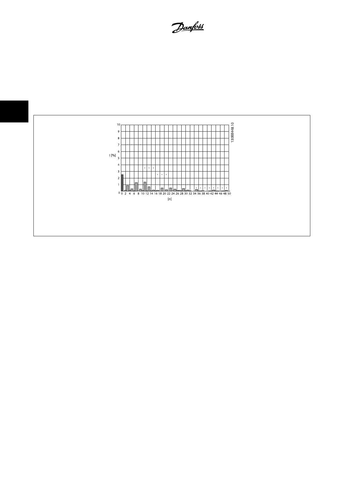
Figure 3.2: Typical harmonic frequency spectrum and THD value at the line power terminals of the drive
n = harmonic order
.....IEEE519
(Isc/IL>20) limits for individual harmonics
3 Introduction to the Low Harmonic Drive
VLT AQUA Low Harmonic Drive Instruction
Manual
3-2
MG.20.T1.22 - VLT
®
is a registered Danfoss trademark
3
 Loading...


