EasyManuals Logo

Danfoss vlt aqua Instruction

Danfoss vlt aqua
206 pages
To Next Page IconTo Next Page
To Previous Page IconTo Previous Page
Page #37 background imageLoading...
Page #37 background image
NOTE!
Power connections can be made to positions A or B
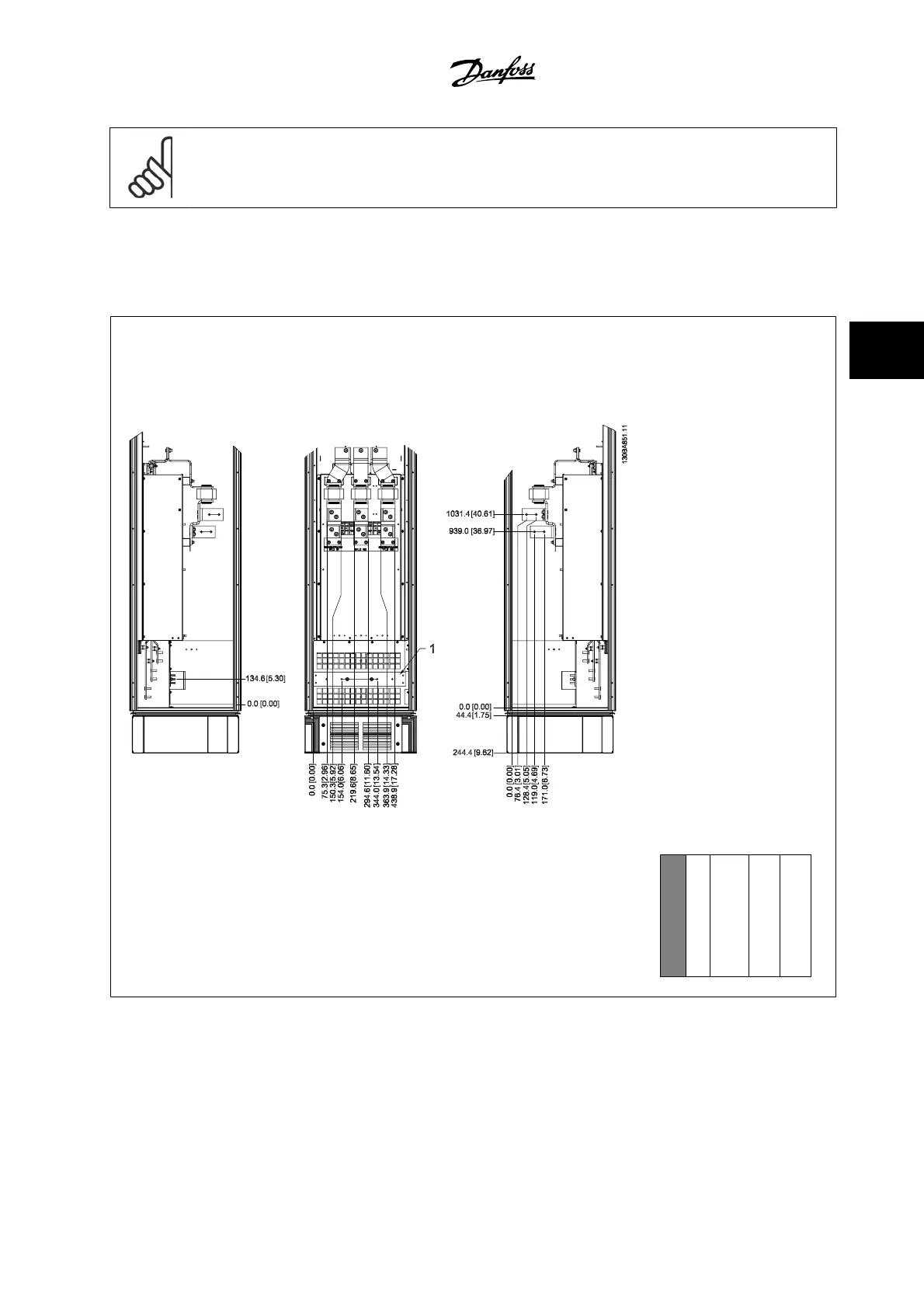
4.3.7 Terminal Locations - Frame size F
Terminal locations - Filter
Figure 4.17: Terminal locations - Filter (left side, front and right side view). The connector plate is 1.65 in
[42 mm] below .0 level.
1) Ground bar
Section shown
VLT AQUA Low Harmonic Drive Instruction
Manual
4 How to Install
MG.20.T1.22 - VLT
®
is a registered Danfoss trademark
4-21
4

Table of Contents

Other manuals for Danfoss vlt aqua

Questions and Answers:

Question and Answer IconNeed help?

Do you have a question about the Danfoss vlt aqua and is the answer not in the manual?

Danfoss vlt aqua Specifications

General IconGeneral
Supply Voltage200-240V, 380-500V, 525-600V
EnclosureIP20
FeaturesEnergy optimization
ApprovalsCE, UL, cUL
Input Voltage Range200-240V, 380-500V, 525-600V
Output Voltage Range0 to supply voltage
Protection FeaturesOvervoltage, Undervoltage, Overcurrent, Short circuit, Ground fault
Communication InterfacesPROFIBUS
Cooling MethodAir-cooled

Related product manuals