EasyManuals Logo

Danfoss vlt aqua Instruction

Danfoss vlt aqua
206 pages
To Next Page IconTo Next Page
To Previous Page IconTo Previous Page
Page #36 background imageLoading...
Page #36 background image
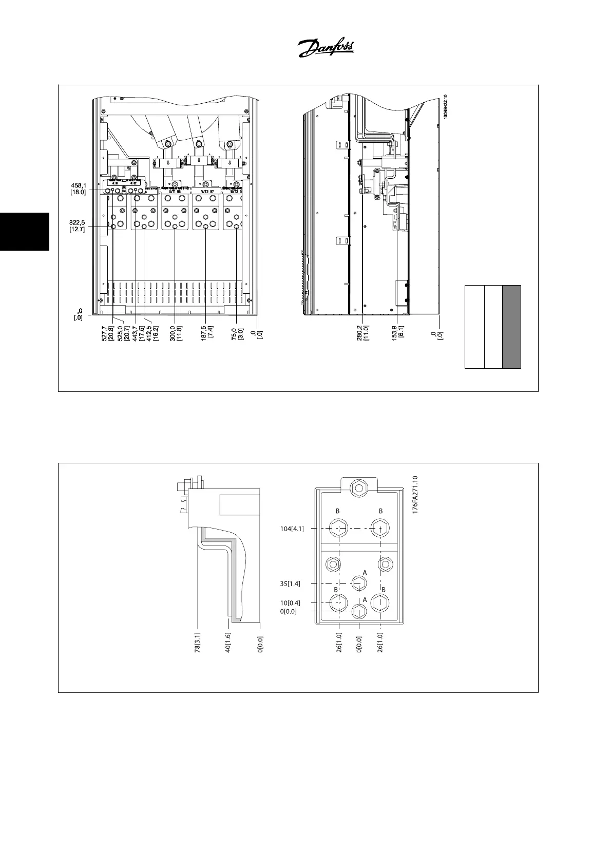
Figure 4.15: Terminal locations E6 - drive
Section shown
Note that the power cables are heavy and difficult to bend. Give thought to the optimum position of the adjustable frequency drive for ensuring easy
installation of the cables.
Each terminal allows for the use of up to 4 cables with cable lugs or the use of standard box lug. Ground is connected to relevant termination point in
the drive.
Figure 4.16: Terminal in details
4 How to Install
VLT AQUA Low Harmonic Drive Instruction
Manual
4-20
MG.20.T1.22 - VLT
®
is a registered Danfoss trademark
4

Table of Contents

Other manuals for Danfoss vlt aqua

Questions and Answers:

Question and Answer IconNeed help?

Do you have a question about the Danfoss vlt aqua and is the answer not in the manual?

Danfoss vlt aqua Specifications

General IconGeneral
Supply Voltage200-240V, 380-500V, 525-600V
EnclosureIP20
FeaturesEnergy optimization
ApprovalsCE, UL, cUL
Input Voltage Range200-240V, 380-500V, 525-600V
Output Voltage Range0 to supply voltage
Protection FeaturesOvervoltage, Undervoltage, Overcurrent, Short circuit, Ground fault
Communication InterfacesPROFIBUS
Cooling MethodAir-cooled

Related product manuals