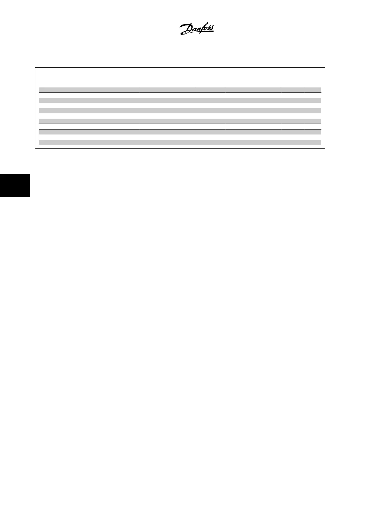
6.5.4 Special Functions 14-**
Par.
No. #
Parameter description Default value
(SR = Size related)
4 set-up FC 302
only
Change dur-
ing opera-
tion
Conver-
sion index
Type
14-2* Trip Reset
14-20 Reset Mode [0] Manual reset All set-ups TRUE - Uint8
14-21 Automatic Restart Time 10 s All set-ups TRUE 0 Uint16
14-22 Operation Mode [0] Normal operation All set-ups TRUE - Uint8
14-23 Typecode Setting null 2 set-ups FALSE - Uint8
14-28 Production Settings [0] No action All set-ups TRUE - Uint8
14-29 Service Code 0 N/A All set-ups TRUE 0 Int32
14-5* Environment
14-50 RFI filter [1] On 1 set-up FALSE - Uint8
14-53 Fan Monitor [1] Warning All set-ups TRUE - Uint8
14-54 Bus Partner 1 N/A 2 set-ups TRUE 0 Uint16
6 How to Program the Low Harmonic Drive
VLT AQUA Low Harmonic Drive Instruction
Manual
6-68
MG.20.T1.22 - VLT
®
is a registered Danfoss trademark
6
 Loading...


