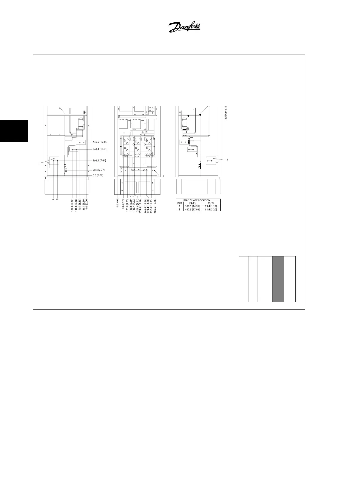
Terminal locations - Rectifier
Figure 4.18: Terminal locations - Rectifier (left side, front and right side view). The connector plate is 1.65
in [42 mm] below .0 level.
1) Load Share Terminal (-)
2) Ground bar
3) Load Share Terminal (+)
Section shown
↓
4 How to Install
VLT AQUA Low Harmonic Drive Instruction
Manual
4-22
MG.20.T1.22 - VLT
®
is a registered Danfoss trademark
4
 Loading...


