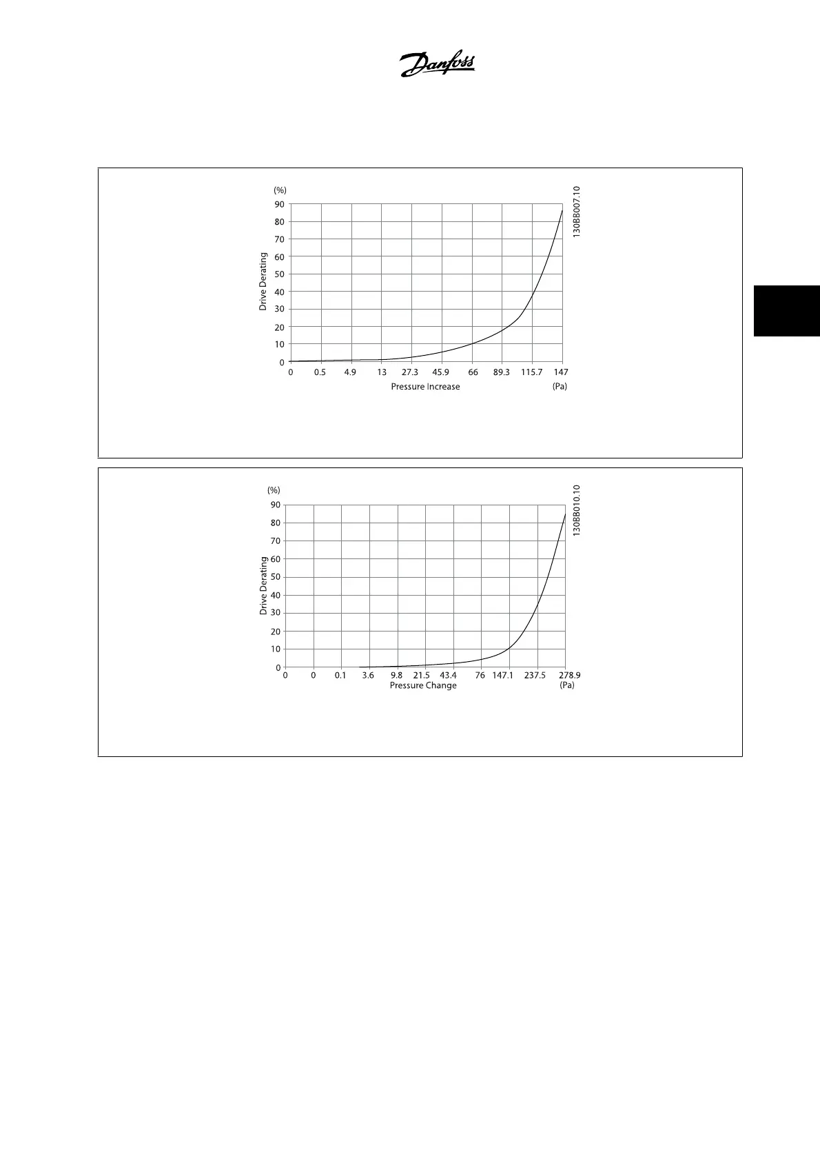
EasyManuals Logo

Danfoss vlt aqua Instruction

Danfoss vlt aqua
206 pages
To Next Page IconTo Next Page
To Previous Page IconTo Previous Page
Page #41 background imageLoading...
Page #41 background image
External ducts
If additional duct work is added externally to the Rittal cabinet, the pressure drop in the ducting must be calculated. Use the charts below to derate the
adjustable frequency drive according to the pressure drop.
Figure 4.20: D frame Derating vs. Pressure Change
Drive air flow: 450 cfm (765 m
3
/h)
Figure 4.21: E frame Derating vs. Pressure Change (Small Fan), P315
Drive air flow: 650 cfm (1105 m
3
/h)
VLT AQUA Low Harmonic Drive Instruction
Manual
4 How to Install
MG.20.T1.22 - VLT
®
is a registered Danfoss trademark
4-25
4

Table of Contents

Other manuals for Danfoss vlt aqua

Questions and Answers:

Question and Answer IconNeed help?

Do you have a question about the Danfoss vlt aqua and is the answer not in the manual?

Danfoss vlt aqua Specifications

General IconGeneral
Supply Voltage200-240V, 380-500V, 525-600V
EnclosureIP20
FeaturesEnergy optimization
ApprovalsCE, UL, cUL
Input Voltage Range200-240V, 380-500V, 525-600V
Output Voltage Range0 to supply voltage
Protection FeaturesOvervoltage, Undervoltage, Overcurrent, Short circuit, Ground fault
Communication InterfacesPROFIBUS
Cooling MethodAir-cooled

Related product manuals