5.1.11 RS-485 Bus Connection
Both filter portion and adjustable frequency drive can be connected to a
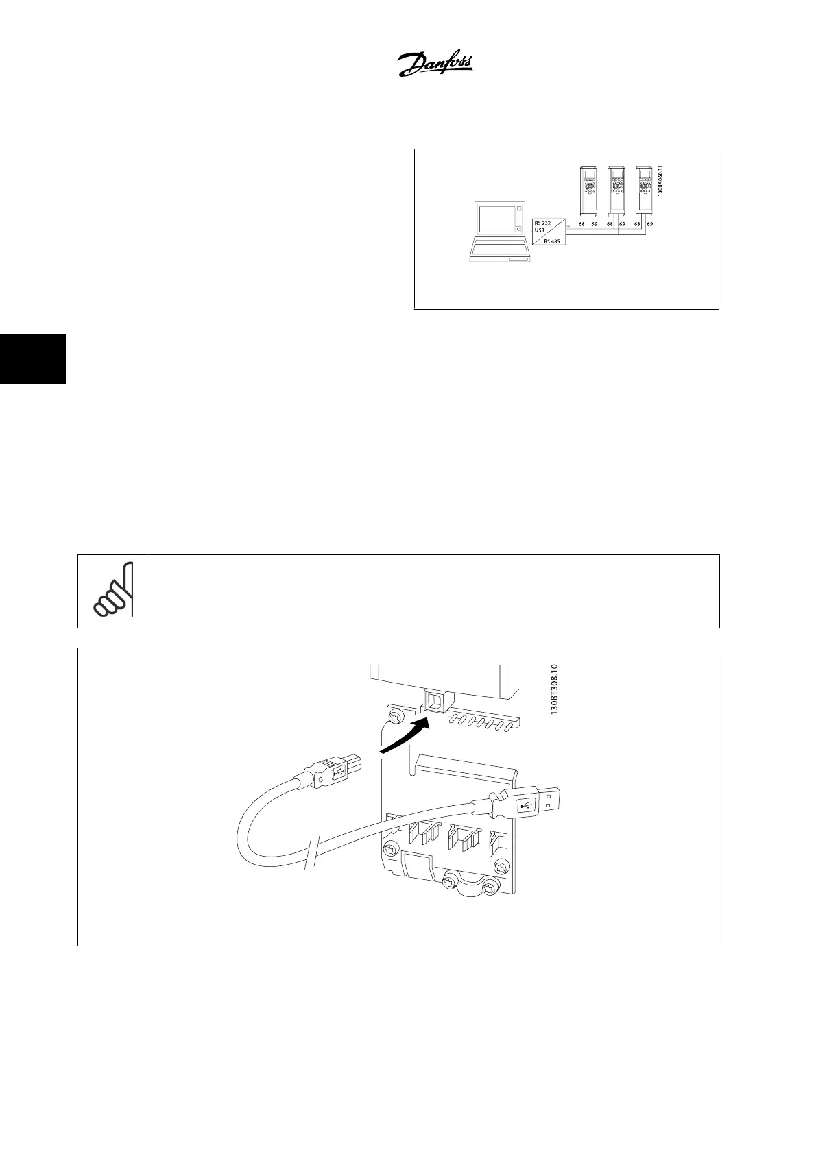
controller (or master) together with other loads using the RS-485 stand-
ard interface. Terminal 68 is connected to the P signal (TX+, RX+), while
terminal 69 is connected to the N signal (TX-,RX-).
Always use parallel connections for the low harmonic drive to ensure that
both filter and drive part are connected..
Figure 5.4: Connection example.
In order to avoid potential equalizing currents in the shield, ground the cable shield via terminal 61, which is connected to the frame via an RC link.
Bus termination
The RS-485 bus must be terminated by a resistor network at both ends. If the drive is the first or the last device in the RS-485 loop, set the switch S801
on the control card to ON.
For more information, see the paragraph
Switches S201, S202, and S801
.
5.1.12 How to connect a PC to the adjustable frequency drive
To control or program the adjustable frequency drive (and the filter part) from a PC, install the PC-based configuration tool MCT 10.
The PC is connected via a standard (host/device) USB cable to both devices, or via the RS-485 interface as shown in the
Design Guide, chapter How to
Install > Installation of misc. connections
.
NOTE!
The USB connection is galvanically isolated from the supply voltage (PELV) and other high-voltage terminals. The USB connection is
connected to protection ground on the adjustable frequency drive. Use only an isolated laptop as PC connection to the USB connector
on the adjustable frequency drive.
Figure 5.5: For control cable connections, see section on
Control Terminals
.
5 How to Operate the Low Harmonic Drive
VLT AQUA Low Harmonic Drive Instruction
Manual
5-10
MG.20.T1.22 - VLT
®
is a registered Danfoss trademark
5

 Loading...


