Q3-4 Application Settings
Q3-40 Fan Functions Q3-41 Pump Functions Q3-42 Compressor Functions
22-60 Broken Belt Function 22-20 Low Power Auto Setup 1-03 Torque Characteristics
22-61 Broken Belt Torque 22-21 Low Power Detection 1-71 Start Delay
22-62 Broken Belt Delay 22-22 Low Speed Detection 22-75 Short Cycle Protection
4-64 Semi-auto Bypass Setup 22-23 No-flow Function 22-76 Interval Between Starts
1-03 Torque Characteristics 22-24 No-flow Delay 22-77 Minimum Run Time
22-22 Low Speed Detection 22-40 Minimum run time 5-01 Terminal 27 Mode
22-23 No-flow Function 22-41 Minimum sleep time 5-02 Terminal 29 Mode
22-24 No-flow Delay 22-42 Wake-up speed [RPM] 5-12 Terminal 27 Digital Input
22-40 Minimum Run Time 22-43 Wake-up speed [Hz] 5-13 Terminal 29 Digital Input
22-41 Minimum Sleep Time 22-44 Wake-up Ref / FB Difference 5-40 Function Relay
22-42 Wake-up Speed [RPM] 22-45 Setpoint Boost 1-73 Flying Start
22-43 Wake-up Speed [Hz] 22-46 Maximum Boost Time 1-86 Trip Speed Low [RPM]
22-44 Wake-up Ref / FB Difference 22-26 Dry Pump Function 1-87 Trip Speed Low [Hz]
22-45 Setpoint Boost 22-27 Dry Pump Delay
22-46 Maximum Boost Time 22-80 Flow Compensation
2-10 Brake function 22-81 Square-linear Curve Approximation
2-16 AC Brake Max. Current 22-82 Work Point Calculation
2-17 Over-voltage control 22-83 Speed at No-Flow [RPM]
1-73 Flying start 22-84 Speed at No-Flow [Hz]
1-71 Start delay 22-85 Speed at Design Point [RPM]
1-80 Function at stop 22-86 Speed at Design Point [Hz]
2-00 DC Hold/preheat Current 22-87 Pressure at No-Flow Speed
4-10 Motor Speed Direction 22-88 Pressure at Rated Speed
22-89 Flow at Design Point
22-90 Flow at Rated Speed
1-03 Torque Characteristics
1-73 Flying Start
See also
VLT HVAC Drive Programming Guide
for a detailed description of the Function Setups parameter groups.
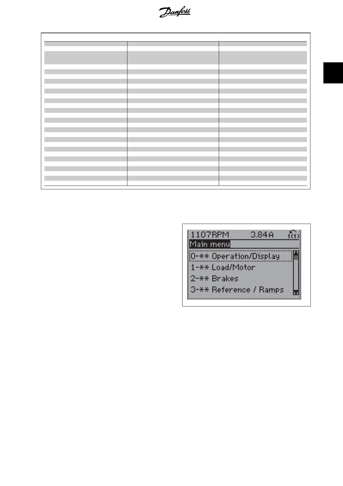
2.1.7. Main Menu Mode
Select the Main Menu mode by pressing the [Main Menu] key. The below
read-out appears on the display.
The middle and bottom sections on the display show a list of parameter
groups which can be chosen by toggling the up and down buttons.
1
Each parameter has a name and number which remain the same regardless of the programming mode. In the Main Menu mode, the parameters are
divided into groups. The first digit of the parameter number (from the left) indicates the parameter group number.
All parameters can be changed in the Main Menu. However, depending on the choice of configuration (par. 1-00), some parameters can be hidden.
VLT
®
HVAC Drive Programming Guide 2. How to Programme
MG.11.C5.02 - VLT
®
is a registered Danfoss trademark
19
2
 Loading...


