Status display III:
This state displays the event and action of the Smart Logic Control. For
further information, see section
Smart Logic Control
.
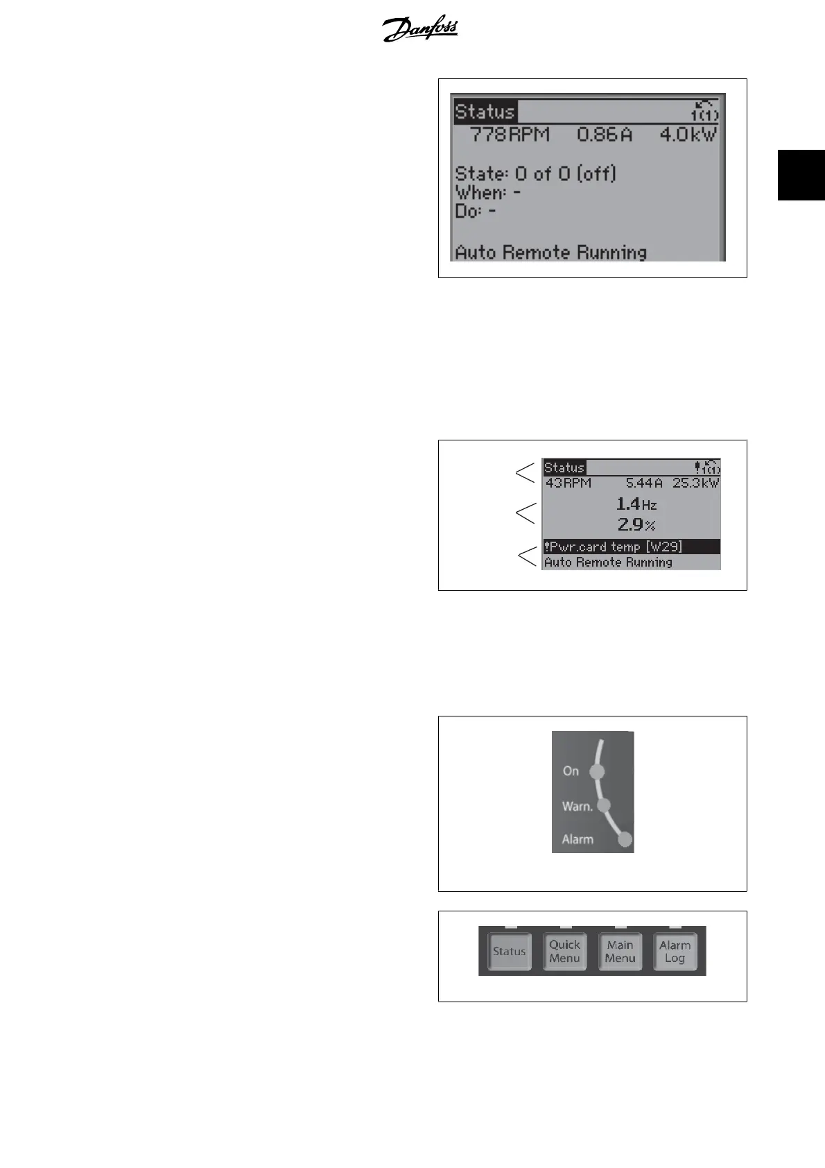
1
The Bottom section always shows the state of the frequency converter
in Status mode.
Display Contrast Adjustment
Press [status] and [ ] for darker display
▲
Press [status] and [ ] for brighter display▼
130BP074.10
Top section
Middle section
Bottom section
Indicator lights (LEDs):
If certain threshold values are exceeded, the alarm and/or warning LED lights up. A status and alarm text appear on the control panel.
The On LED is activated when the frequency converter receives power from mains voltage, a DC bus terminal, or an external 24 V supply. At the same
time, the back light is on.
• Green LED/On: Control section is working.
• Yellow LED/Warn.: Indicates a warning.
• Flashing Red LED/Alarm: Indicates an alarm.
130BP040.10
GLCP keys
Menu keys
The menu keys are divided into functions. The keys below the display and
indicator lamps are used for parameter set-up, including choice of display
indication during normal operation.
130BP045.10
VLT
®
HVAC Drive Programming Guide 2. How to Programme
MG.11.C5.02 - VLT
®
is a registered Danfoss trademark
7
2
 Loading...


