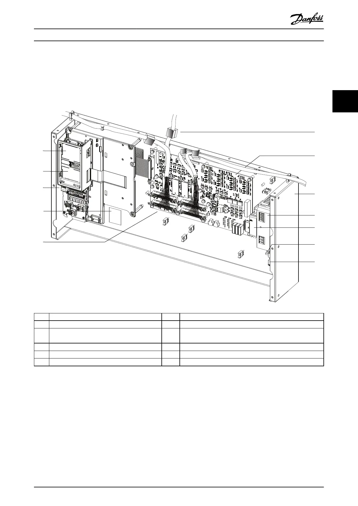
3.3 Control Shelf
The control shelf contains the LCP, MDCIC, and control card. The LCP provides access to the system parameters. The MDCIC
is connected to each of the drive modules via a ribbon cable and communicates to the control card. The control card
controls the operation of the drive modules.
1 LCP cradle 7 MDCIC card
2 Control card (underneath cover) 8 Control shelf
3 Control terminal blocks 9 Switch mode power supply (SMPS). Note that an external 230 V
supply is needed to power the SMPS.
4 Top-level drive system label. See Illustration 4.1. 10 Pilz relay
5 44-pin cables from MDCIC board to drive modules 11 DIN rail
6 Ferrite core 12 Terminal block mounted on DIN rail
Illustration 3.2 Control Shelf
Product Overview Installation Guide
MG37K302 Danfoss A/S © 08/2017 All rights reserved. 9
3 3
 Loading...


