6.4 Conguring the Drive System
Before the drive system is fully functional, it is necessary to
congure the unit on the local control panel (LCP). The
top-level drive system label is needed for the following
steps. Refer to Illustration 4.1.
1. Apply power. At power-up, the LCP display shows
alarm 250, New spare part.
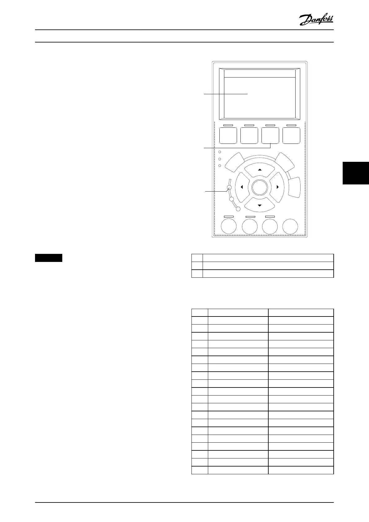
2. Press [Main Menu] twice on the LCP. See
Illustration 6.1.
3. Press the navigation keys and the [OK] key to
navigate to parameter group 14-** Special
Functions. Then scroll down to
parameter 14-23 Typecode Setting.
4. Scroll through the submenu to match the 39
characters in the typecode to the 20 index
groups. See Table 6.2. Press [OK] to enter the
value.
5. At index number 20, select Save to EEPROM and
press [OK]. When the system nishes writing the
EEPROM data, the display shows No Function.
6. Remove power to the drive system, and then
reapply power. Press [RESET] to clear the alarm.
NOTICE
INCORRECT TYPECODE ENTERED
If the wrong typecode is entered, scroll to
parameter 14-29 Service Code and enter 00006100. This
step allows access to parameter 14-23 Typecode Setting to
reenter the typecode.
130BE712.10
Auto
on
Reset
Hand
on
O
Status
Quick
Menu
Main
Menu
Alarm
Log
Back
Cancel
Info
OK
On
Alarm
Warn.
1
3
2
1 LCP display
2 [Main Menu] key
3 Power-on indicator light
Illustration 6.1 Local Control Panel (LCP)
Index Description Typecode units
[0] Product group 1–3
[1] Series 4–6
[2] Power 7–10
[3] Voltage 11–12
[4] Enclosure 13–15
[5] RFI lter 16–17
[6] Brake & stop 18
[7] Display 19
[8] Coating 20
[9] Mains options 21
[10] Adaptation A 22
[11] Adaptation B 23
[12] Software 24–27
[13] Language 28
[14] Options A 29–30
[15] Options B 31–32
[16] Options C0 33–34
[17] Options C1 35
[18] Options C 36–37
[19] Options D 38–39
Table 6.2 Typecode Index
Initial Start-up Installation Guide
MG37K302 Danfoss A/S © 08/2017 All rights reserved. 43
6
6
 Loading...


