5.10.1 Control Cable Routing
Cable routing
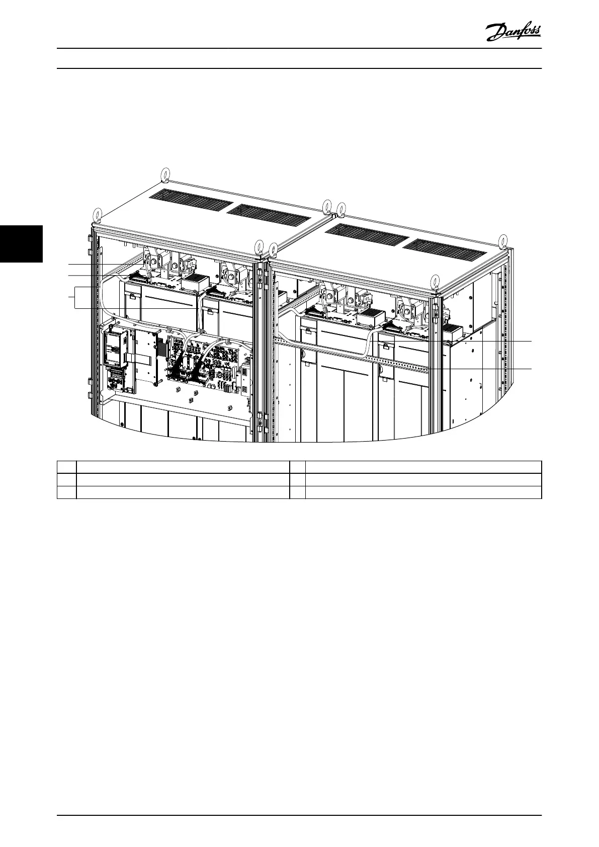
Route the cable inside the drive cabinets as shown in Illustration 5.8. Wire routing for a 2-drive conguration is identical,
except for the number of drive modules used.
1 Microswitch cable 4 44-pin ribbon cable from MDCIC to drive module 4
2 Ferrite core 5 Bracket to support ribbon cable
3 44-pin ribbon cable from MDCIC to drive modules 1 and 2 – –
Illustration 5.8 Control Cable Routing for a 4-Drive System
Electrical Installation
VLT
®
Parallel Drive Modules
32 Danfoss A/S © 08/2017 All rights reserved. MG37K302
55
 Loading...


