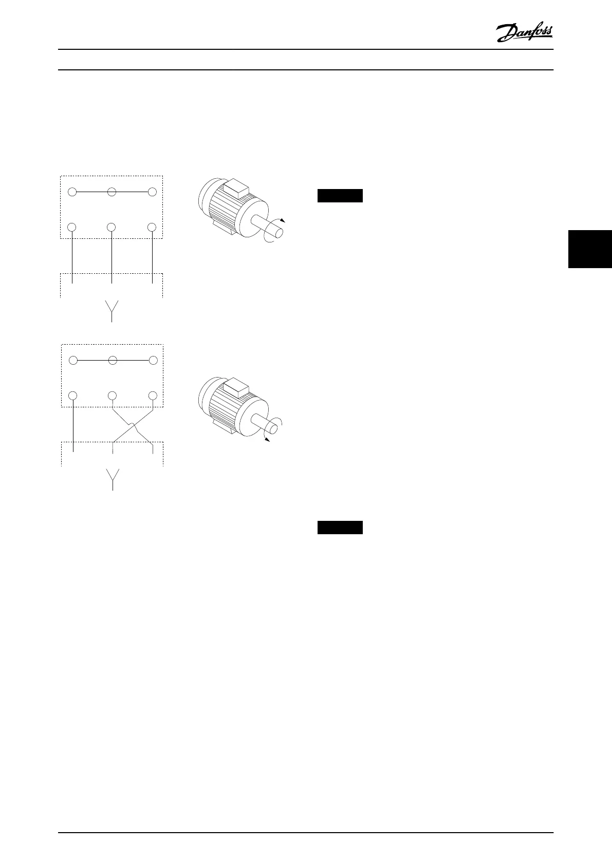
Changing motor rotation
•
Terminal U/T1/96 connected to U-phase
•
Terminal V/T2/97 connected to V-phase
•
Terminal W/T3/98 connected to W-phase
175HA036.11
U
1
V
1
W
1
96 97 98
FC
Motor
U
2
V
2
W
2
U
1
V
1
W
1
96 97 98
FC
Motor
U
2
V
2
W
2
Illustration 5.7 Changing Motor Rotation
The direction of rotation can be changed by switching 2
phases in the motor cable, or by changing the setting of
parameter 4-10 Motor Speed Direction.
Motor rotation check can be performed using
parameter 1-28 Motor Rotation Check and following the
steps shown in Illustration 5.7.
5.7.3.2 Motor Terminal Connections in 2-
Drive Module Systems
Illustration 8.9 and Illustration 8.10 show the bus bar
connections for 6-pulse and 12-pulse 2-drive systems,
respectively. If a common terminal design is used, there is
1 set of motor terminals.
NOTICE
MULTIPLE MOTOR CABLES
If connecting more than 1 set of motor terminals, use
the same number, size, and length of cables for each set
of terminals. For example, do not use 1 cable on one
motor terminal and 2 cables on another motor terminal.
1. Measure between the common terminals and the
rst common point of a phase, typically the
motor terminals.
2. Strip a section of the outer cable insulation.
3. Connect the ground wire to the nearest
protective earth terminal.
4. Connect the 3-phase motor wiring to terminals
U/96, V/97, and W/98 using M10 screws.
5. Tighten the motor terminals. See
chapter 7.9.1 Tightening Torques for Terminals.
5.7.3.3 Motor Terminal Connections in 4-
Drive Module Systems
Illustration 8.11 shows the bus bar connections for a 4-drive
system. If a common terminal design is used, there is 1 set
of motor terminals in each cabinet.
NOTICE
MULTIPLE MOTOR CABLES
If connecting more than 1 set of motor terminals, use
the same number, size, and length of cables for each set
of terminals. For example, do not use 1 cable on one
motor terminal and 2 cables on another motor terminal.
1. Measure between the common terminals and the
rst common point of a phase, typically the
motor terminals.
2. Strip a section of the outer cable insulation.
3. Connect the ground wire to the nearest
protective earth (ground) terminal.
4. Connect the 3-phase motor wiring to terminals
U/96, V/97, and W/98 using M10 screws.
5. Tighten the motor terminals. See
chapter 7.9.1 Tightening Torques for Terminals.
Electrical Installation Installation Guide
MG37K302 Danfoss A/S © 08/2017 All rights reserved. 27
5 5

 Loading...


