EasyManuals Logo

Danfoss vlt FC 102 Installation Guide

Danfoss vlt FC 102
84 pages
To Next Page IconTo Next Page
To Previous Page IconTo Previous Page
Page #80 background imageLoading...
Page #80 background image
8.3.11 Connections in a 4-Drive Module System
e30be744.11
R/
91
S/
92
T/
93
U/
96
V/
97
W/
98
R
+
R
-
R/
91
S/
92
T/
93
U/
96
V/
97
W/
98
R
+
R
-
R/
91
S/
92
T/
93
U/
96
V/
97
W/
98
R
+
R
-
R/
91
S/
92
T/
93
U/
96
V/
97
W/
98
R
+
R
-
1
2
3
4
5
6
7
8
9
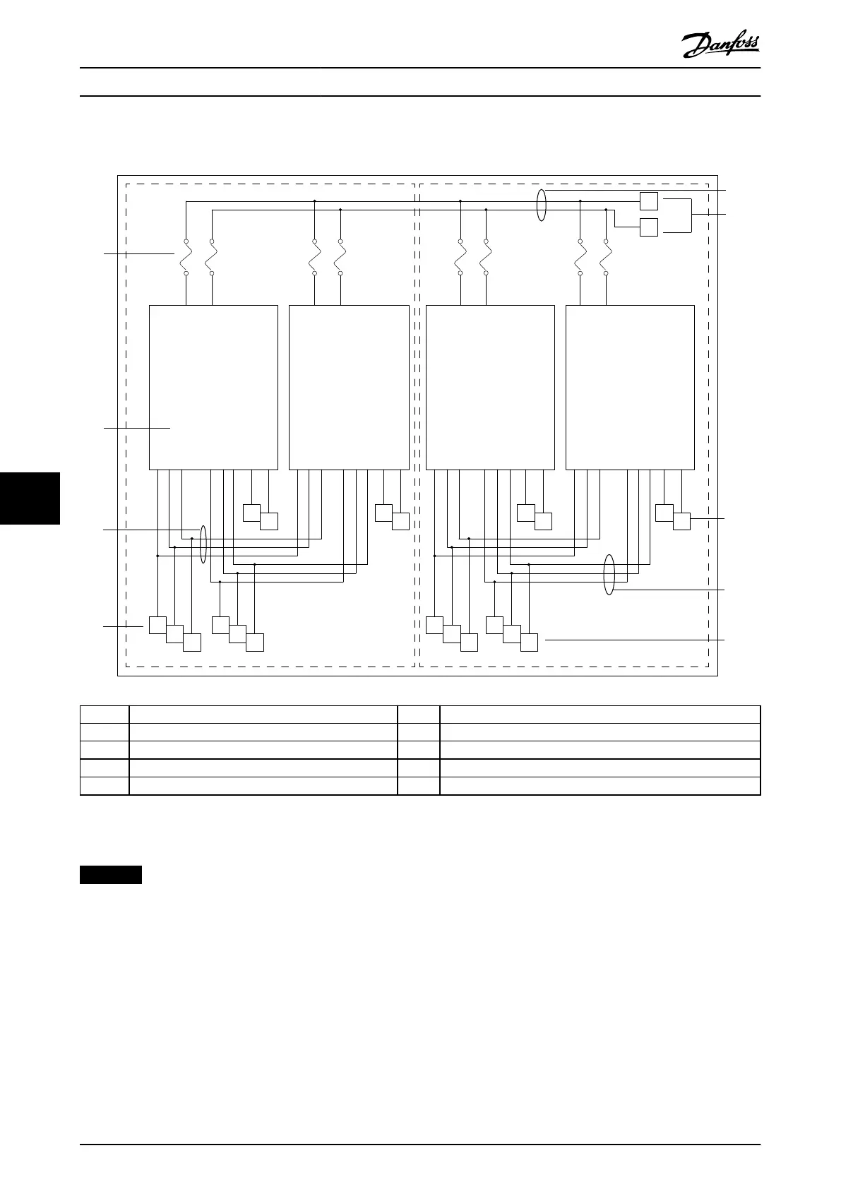
1 DC fuses 6 DC terminals
2 Drive module 7 Connection to brake
3 Mains input bus bars connecting 2 drive modules 8 Motor output bus bars connecting 2 drive modules
4 Connection to mains input 9 Connection to motor output
5 DC-link bus bars connecting all 4 drive modules
Illustration 8.11 Connections in a 4-Drive Module System
NOTICE
DRIVE MODULE WIRING
The installer must install an equal number of wires to
each set of drive modules.
Appendix
VLT
®
Parallel Drive Modules
78 Danfoss A/S © 08/2017 All rights reserved. MG37K302
88

Table of Contents

Other manuals for Danfoss vlt FC 102

Questions and Answers:

Question and Answer IconNeed help?

Do you have a question about the Danfoss vlt FC 102 and is the answer not in the manual?

Danfoss vlt FC 102 Specifications

General IconGeneral
CategoryDC Drives
ModelDanfoss VLT FC 102
Output voltage range0 to rated motor voltage
Power range0.37 kW to 200 kW
Communication interfacesRS-485
Protection featuresOvervoltage, undervoltage, overcurrent, short circuit, earth fault, overtemperature, motor thermal protection
Cooling methodAir-cooled
Enclosure ratingIP20, IP21, IP55 (depending on model)
ApprovalsCE, UL, cUL

Related product manuals