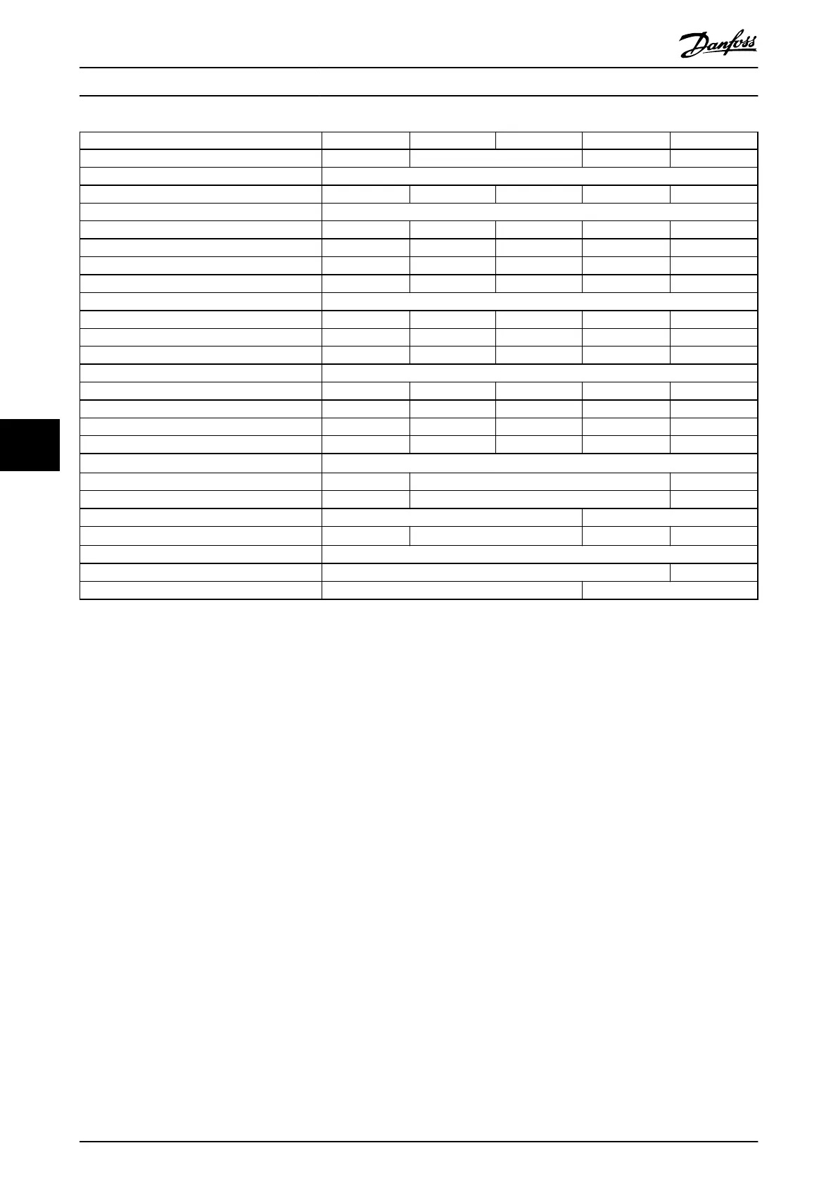
Power range N710 N800 N900 N1M0 N1M2
Drive modules 4 4 4 4
Rectier conguration 6-pulse/12-pulse
High/normal load NO NO NO NO NO
Output current [A]
Continuous (at 550 V) 763 889 988 1108 1317
Intermittent (60 s overload) at 550 V 839 978 1087 1219 1449
Continuous (at 575/690 V) 730 850 945 1060 1260
Intermittent (60 s overload) at 575/690 V 803 935 1040 1166 1590
Input current [A]
Continuous (at 550 V) 743 866 962 1079 1282
Continuous (at 575 V) 711 828 920 1032 1227
Continuous (at 690 V) 711 828 920 1032 1227
Power losses [W]
Drive modules at 575 V 8683 10166 11406 12852 15762
Drive modules at 690 V 8559 9996 11188 12580 15358
AC bus bars at 575 V 644 653 661 672 695
DC bus bars during regeneration 198 208 218 231 256
Maximum cable size [mm
2
(mcm)]
Mains 4x120 (250) 6x120 (250) 8x120 (250)
Motor 4x120 (250) 6x120 (250) 8x120 (250)
Brake 8x70 (2/0) 8x95 (3/0)
Regeneration terminals
1)
4x150 (300) 6x120 (250) 6x150 (300) 8x120 (250)
Maximum external mains fuses
6-pulse conguration 700 V, 1600 A 700 V, 2000 A
12-pulse conguration 700 V, 900 A 700 V, 1500 A
Table 7.4 FC 102, 525–690 V AC Mains Supply (4-Drive System)
1) If Danfoss bus bar kit is used.
Specications
VLT
®
Parallel Drive Modules
48 Danfoss A/S © 08/2017 All rights reserved. MG37K302
77
 Loading...


