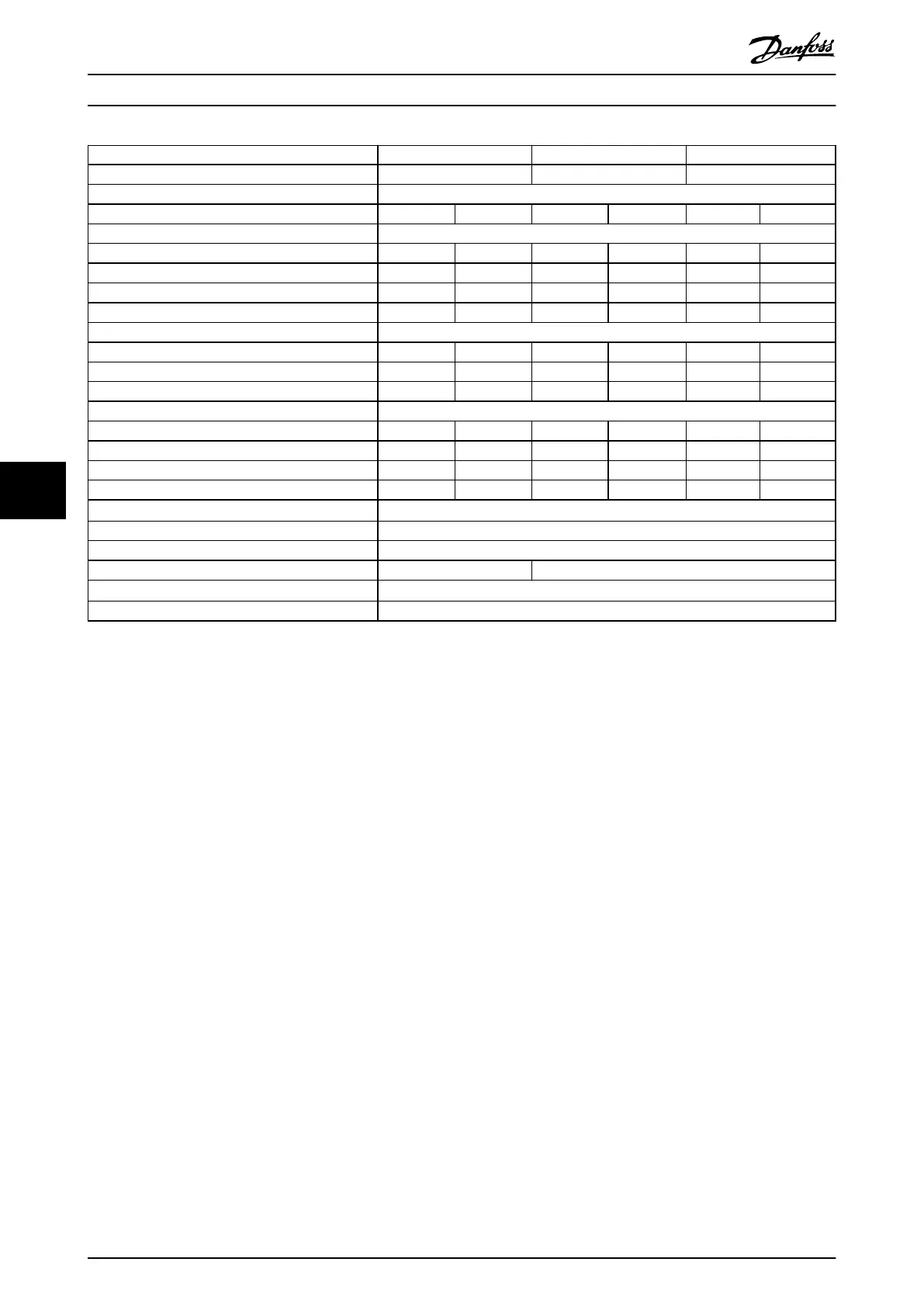
Power range N500 N560 N630
Drive modules 2 2 2
Rectier conguration 12-pulse
High/normal load HO NO HO NO HO NO
Output current [A]
Continuous (at 550 V) 429 523 523 596 596 630
Intermittent (60 s overload) at 550 V 644 575 785 656 894 693
Continuous (at 575/690 V) 410 500 500 570 570 630
Intermittent (60 s overload) at 575/690 V 615 550 750 627 627 693
Input current [A]
Continuous (at 550 V) 413 504 504 574 574 607
Continuous (at 575 V) 395 482 482 549 549 607
Continuous (at 690 V) 395 482 482 549 549 607
Power losses [W]
Drive modules at 575 V 4892 6076 6016 6995 6941 7431
Drive modules at 690 V 4797 5951 5886 6831 6766 7638
AC bus bars at 575 V 542 546 546 550 550 553
DC bus bars during regeneration 91 91 186 186 191 191
Maximum cable size [mm
2
(mcm)]
Mains 4x120 (250)
Motor 4x120 (250)
Brake 4x70 (2/0) 4x95 (3/0)
Regeneration terminals
1)
4x120 (250)
Maximum external mains fuses 700 V, 630 A
Table 7.8 FC 202, 525–690 V AC Mains Supply (2-Drive System)
1) If Danfoss bus bar kit is used.
Specications
VLT
®
Parallel Drive Modules
52 Danfoss A/S © 08/2017 All rights reserved. MG37K302
77
 Loading...


