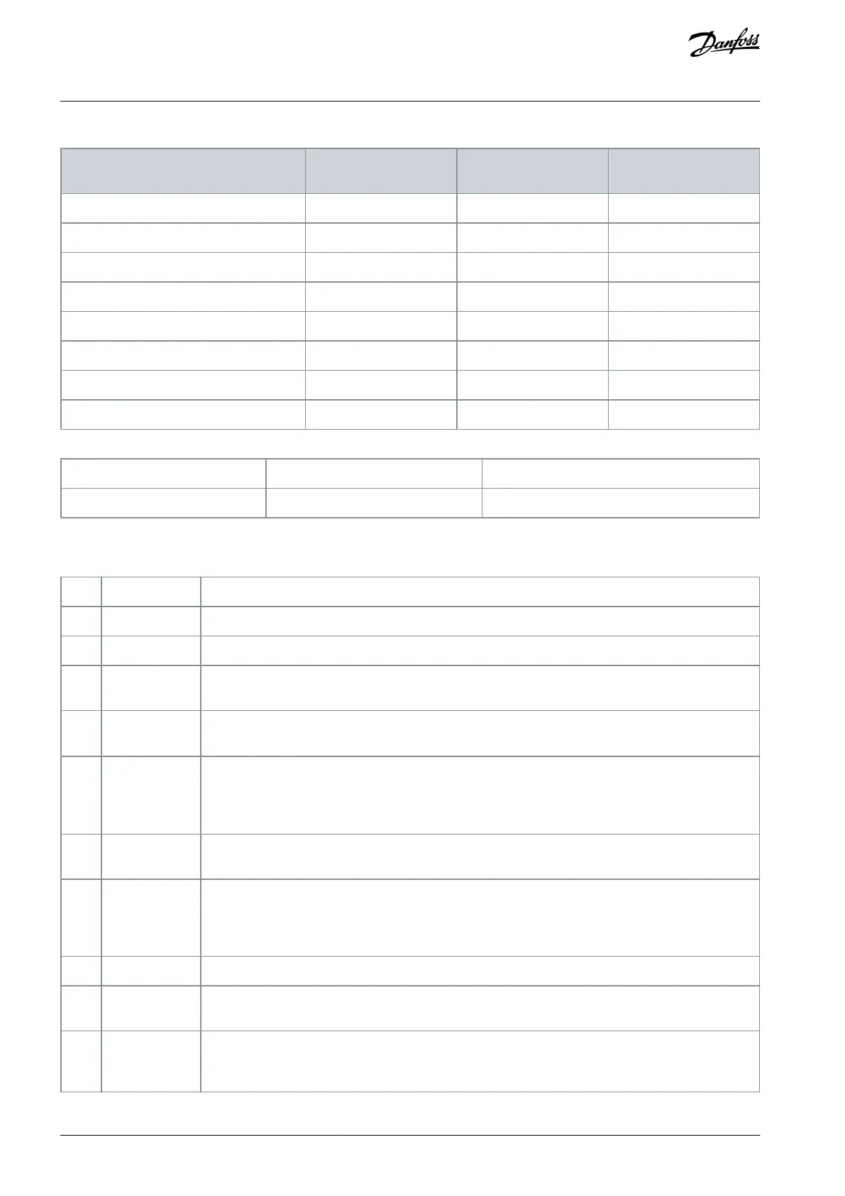
Table 133: Selected Multi Fire Mode Preset Reference (Parameter 24-08 Mul FM Preset Reference)
Selected multi fire mode preset reference:
Fire mode preset reference 0
Fire mode preset reference 1
Fire mode preset reference 2
Fire mode preset reference 3
Fire mode preset reference 4
Fire mode preset reference 5
Fire mode preset reference 6
Fire mode preset reference 7
5-10 Terminal 18 Digital Input
Change during operation: True
Parameter for configuring the input function on input terminal 18.
Table 134: Option:
No reaction to signals transmitted to the terminal.
Reset the drive after a trip/alarm. Trip lock alarms can be reset.
Leave the motor in free mode. Logic 0⇒coast stop.
Reset and coast stop inverted input (NC). Leaves the motor in free mode and resets the drive. Logic
0⇒coast stop and reset.
Inverted input (NC). Generates a stop in accordance with the quick-stop ramp time set in parameter
3-81 Quick Stop Ramp Time. After ramping down, the shaft is in free mode.
Inverted input for DC braking (NC). Stops the motor by energizing it with DC current for a certain time
period, see parameter 2-01 DC Brake Current. The function is only active when the value in parameter
2-02 DC Braking Time is different from 0. This selection is not possible when parameter 1-10 Motor Con-
struction is set to [1] PM non-salient SPM.
The stop inverse function generates the stop function when the selected terminal goes from logical
level 1 to 0 (not latched). Stop is performed according to selected ramp time.
Same function as coast stop, inverse, but external interlock generates the alarm message external fault
on the display when the terminal programmed for coast inverse is logic 0. If programmed for external
interlock, the alarm message is also active via digital outputs and relay outputs. If the cause for the
external interlock is removed, the alarm can be reset using a digital input, fieldbus, or the [Reset] key.
Select start for a start/stop command. Logic 1 = start, logic 0 = stop. (Default digital input 18).
If a pulse is applied for a minimum of 2 ms, the motor starts. The motor stops when stop inverse is
activated.
Change direction of motor shaft rotation. The reversing signal only changes the direction of rotation, it
does not activate the start function. Select [2] Both directions in parameter 4-10 Motor Speed Direction. 0
= normal, 1 = reversing.
AU363928304090en-000101 / 130R098270 | Danfoss A/S © 2021.07
Parameters
VLT® Flow Drive FC 111
Programming Guide
 Loading...


