WARNING/ALARM 4
Line phase loss:
A phase is missing on the supply side, or the
line voltage imbalance is too high.
This message also appears in case of a fault
in the input rectifier on the adjustable fre-
quency drive.
Check the supply voltage and supply currents
to the adjustable frequency drive.
WARNING 5
DC link voltage high:
The intermediate circuit voltage (DC) is higher
than the overvoltage limit of the control sys-
tem. The adjustable frequency drive is still
active.
WARNING 6
DC link voltage low
The intermediate circuit voltage (DC) is below
the undervoltage limit of the control system.
The adjustable frequency drive is still active.
WARNING/ALARM 7
DC overvoltage:
If the intermediate circuit voltage exceeds the
limit, the adjustable frequency drive trips after
a given period of time.
Possible corrections:
Connect a brake resistor
Extend the ramp time
Activate functions in par. 2-10
Increase par. 14-26
Connect a brake resistor. Extend the ramp
time
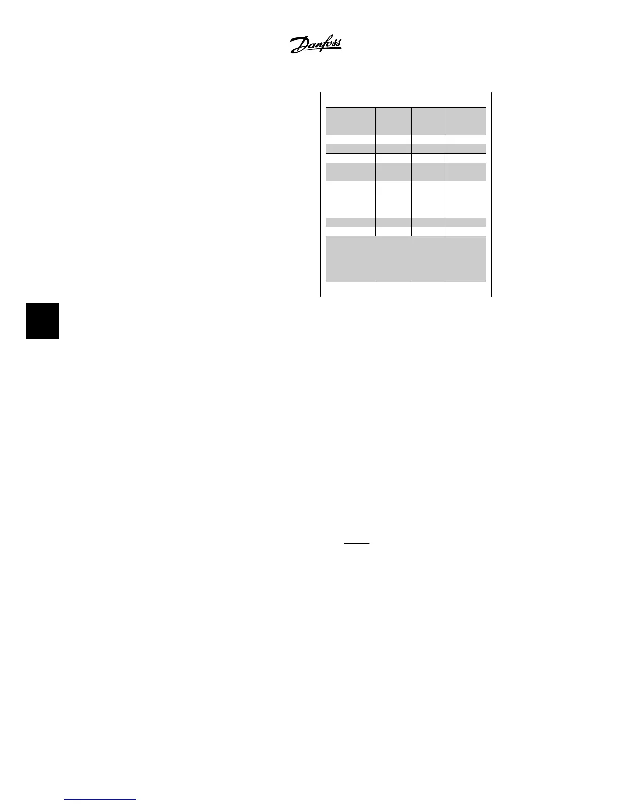
Alarm/warning limits:
Voltage
ranges
3 x
200-240
V
3 x
380-480
V
3 x
525-600 V
[VDC] [VDC] [VDC]
Undervoltage 185 373 532
Voltage
warning low
205 410 585
Voltage
warning high
(w/o brake -
w/brake)
390/405 810/840 943/965
Overvoltage 410 855 975
The voltages stated are the intermediate circuit
voltages of the adjustable frequency drive with
a tolerance of ± 5%. The corresponding line
voltage is the intermediate circuit voltage (DC
link) divided by 1.35.
WARNING/ALARM 8
DC undervoltage:
If the intermediate circuit voltage (DC) drops
below the “voltage warning low” limit (see ta-
ble above), the adjustable frequency drive
checks if 24 V backup supply is connected.
If no 24 V backup supply is connected, the
adjustable frequency drive trips after a given
period of time, depending on the unit.
To check whether the supply voltage matches
the adjustable frequency drive, see
Specifica-
tions
.
WARNING/ALARM 9
Inverter overloaded:
The adjustable frequency drive is about to cut
out because of an overload (too high current
for too long). The counter for electronic, ther-
mal inverter protection gives a warning at
98% and trips at 100%, while giving an alarm.
Reset
cannot be performed before counter is
below 90%.
The fault is that the adjustable frequency
drive is overloaded by more than 100% for too
long.
WARNING/ALARM 10
Motor ETR overtemperature:
According to the electronic thermal protection
(ETR), the motor is too hot. It can be chosen
if the adjustable frequency drive is to give a
warning or an alarm when the counter rea-
ches 100% in par. 1-90. The fault is that the
7. Troubleshooting VLT
®
HVAC Drive Instruction Manual
134
MG.11.A4.22 - VLT
®
is a registered Danfoss trademark
7

 Loading...


