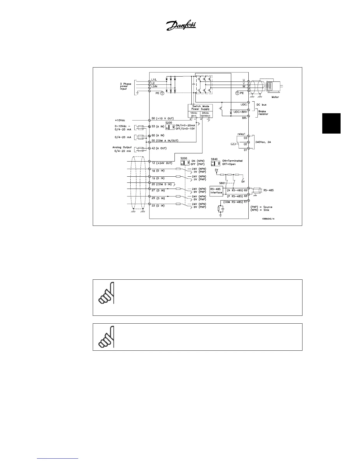
4.1.19. Electrical Installation and Control Cables
Illustration 4.28: Diagram showing all electrical terminals. (Terminal 37 present for units with Safe Stop
function only.)
Very long control cables and analog signals may, in rare cases and depending on the installation,
result in 50/60 Hz ground loops due to noise from line supply cables.
If this occurs, break the shield or insert a 100 nF capacitor between shield and chassis.
NOTE
The common of digital / analog inputs and outputs should be connected to separate
common terminals 20, 39, and 55. This will prevent ground current interference
among groups. For example, it prevents switching on digital inputs from disturbing
analog inputs.
NOTE
Control cables must be shielded/armored.
VLT
®
HVAC Drive Instruction Manual 4. Electrical installation
MG.11.A4.22 - VLT
®
is a registered Danfoss trademark
45
4

 Loading...


