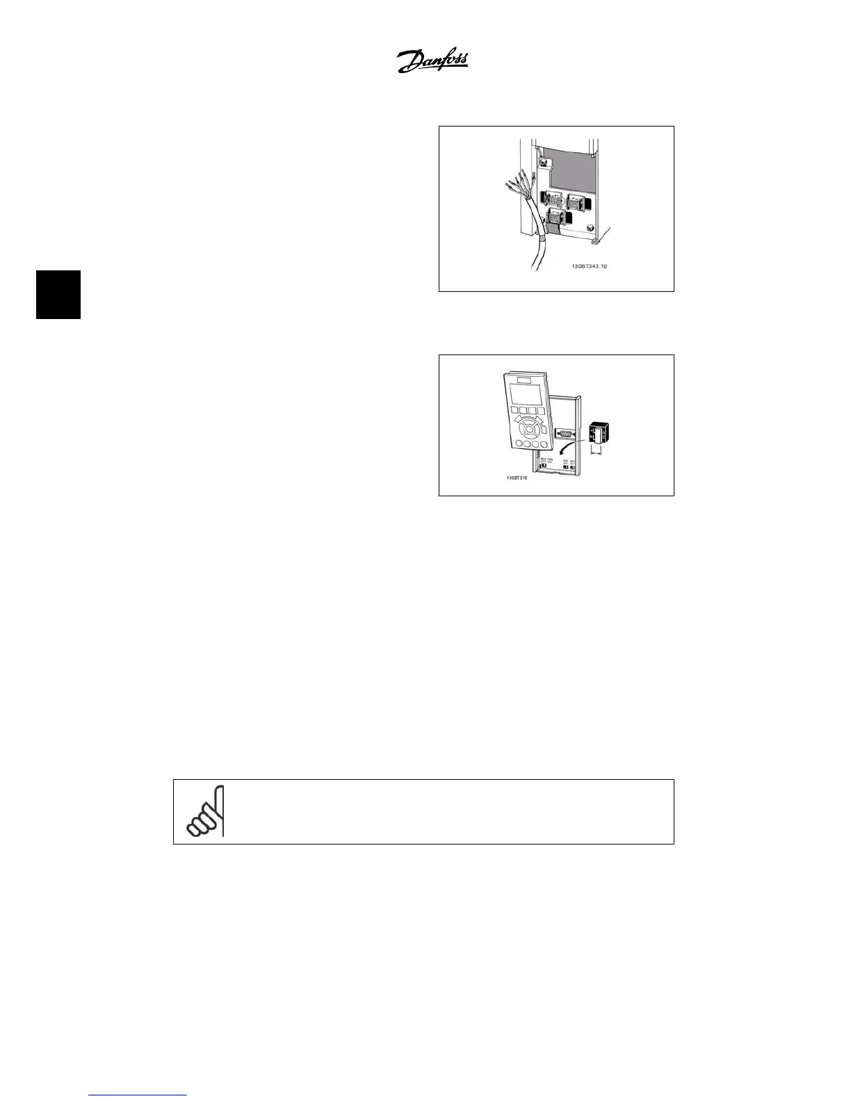
1. Use a clamp from the accessory bag
to connect the shield to the adjusta-
ble frequency drive decoupling plate
for control cables.
See section entitled
Grounding of Shielded/
Armored Control Cables
for the correct termi-
nation of control cables.
Illustration 4.29: Control cable clamp.
4.1.20. Switches S201, S202, and S801
Switches S201 (Al 53) and S202 (Al 54) are
used to select a current (0-20 mA) or a voltage
(0 to 10 V) configuration of the analog input
terminals 53 and 54 respectively.
Switch S801 (BUS TER.) can be used to enable
termination on the RS-485 port (terminals 68
and 69).
Please note that the switches may be covered
by an option, if so equipped.
Default setting:
S201 (AI 53) = OFF (voltage input)
S202 (AI 54) = OFF (voltage input)
S801 (Bus termination) = OFF
Illustration 4.30: Switches location.
4.2. Final optimization and test
4.2.1. Final optimization and test
To optimize motor shaft performance and optimize the adjustable frequency drive for the con-
nected motor and installation, please follow these steps: Ensure that adjustable frequency
driverand motor are connected and that power is applied to adjustable frequency drive.
NOTE
Before power-up, ensure that connected equipment is ready for use.
Step 1. Locate motor nameplate
4. Electrical installation VLT
®
HVAC Drive Instruction Manual
46
MG.11.A4.22 - VLT
®
is a registered Danfoss trademark
4

 Loading...


