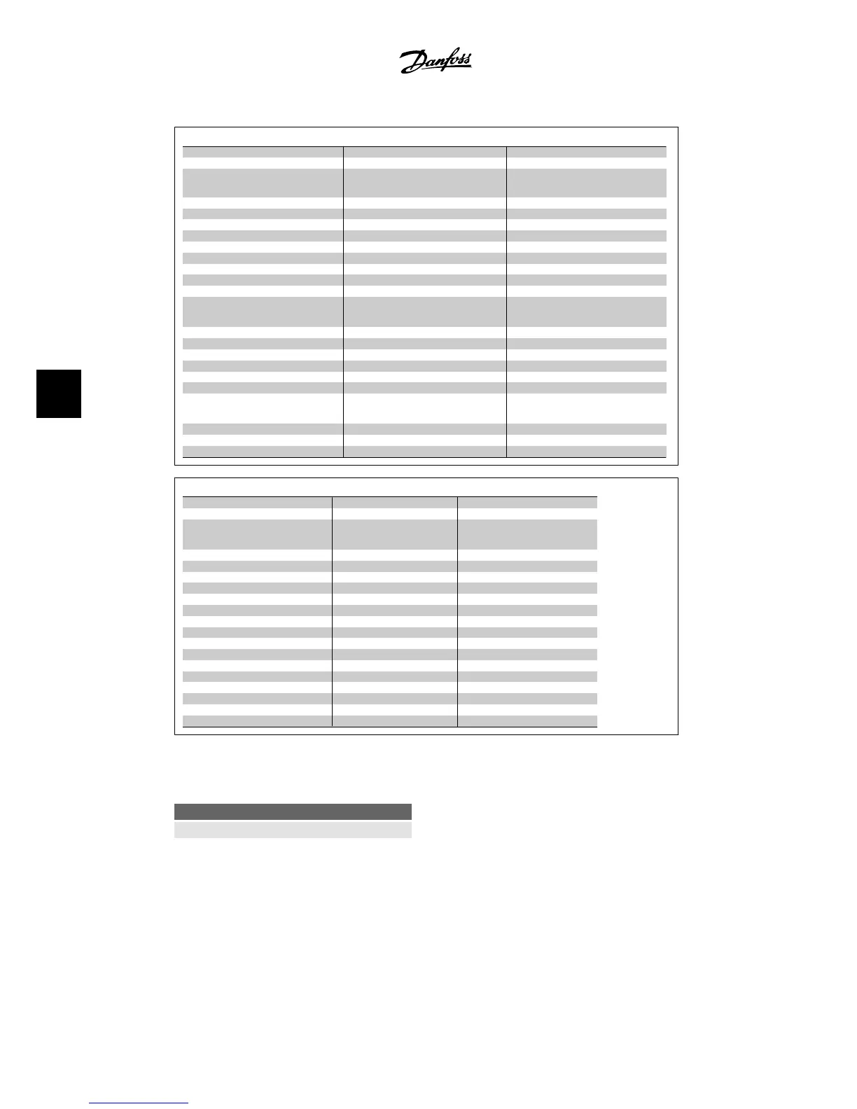
Q3-3 Closed-loop Settings
Q3-30 Single Zone Int. S. Q3-31 Single Zone Ext. S Q3-32 Multi-zone / Adv.
1-00 Configuration mode 1-00 Configuration mode 1-00 Configuration mode
20-12 Reference/feedb unit 20-12 Reference/feedback 20-12 Reference/feedb unit
3-02 Minimum reference 3-02 Minimum reference 3-02 Minimum reference
3-03 Maximum reference 3-03 Maximum reference 3-03 Maximum reference
6-24 Terminal 54 low ref/feedb value 6-10 Terminal 53 low voltage 3-15 Reference 1 source
6-25 Terminal 54 high ref/feedb value 6-11 Terminal 53 high voltage 3-16 Reference 2 source
6-26 Terminal 54 Filter time constant 6-14 Terminal 53 low ref/feedb. value 20-00 Feedback 1 source
6-27 Terminal 54 live zero 6-15 Terminal 53 high ref/feedb. value 20-01 Feedback 1 conversion
6-00 Live zero timeout time 6-24 Terminal 54 low ref/feedb value 20-03 Feedback 1 source
6-01 Live zero timeout function 6-25 Terminal 54 high ref/feedb value 20-04 Feedback 2 conversion
20-81 PID normal/inverse control 6-26 Terminal 54 Filter time constant 20-06 Feedback 3 source
20-82 PID start speed [RPM] 6-27 Terminal 54 live zero 20-07 Feed back 3 conversion
20-21 Setpoint 1 6-00 Live zero timeout time 6-10 Terminal 53 low voltage
20-93 PID proportional gain 6-01 Live zero timeout function 6-11 Terminal 53 high voltage
20-94 PID integral time 20-81 PID normal/inverse control 6-14 Terminal 53 low ref/feedb. value
20-82 PID start speed [RPM] 20-93 PID proportional gain
20-94 PID integral time
4-56 Warning feedback low
4-57 Warning feedback high
20-20 Feedback function
20-21 Setpoint 1
20-22 Setpoint 2
Q3-4 Application Settings
Q3-40 Fan Functions Q3-41 Pump Functions Q3-42 Compressor Functions
22-60 Broken belt function 22-20 Low power auto set-up 1-03 Torque characteristics
22-61 broken belt torque 22-21 Low power detection 1-71 Start delay
22-62 Broken belt delay 22-22 Low speed detection 22-75 Short cycle protection
4-64 Semi-auto bypass set-up 22-23 No-flow function 22-76 Interval between starts
1-03 Torque characteristics 22-24 No-flow delay 22-77 Minimum run time
22-22 Low speed detection 22-40 Minimum run time 5-01 Terminal 27 mode
22-23 No-flow function 22-41 Minimum sleep time 5-02 Terminal 29 mode
22-24 No-flow delay 22-42 Wake-up speed 5-12 Terminal 27 digital input
22-40 Minimum run time 22-26 Dry pump function 5-13 Terminal 29 digital input
22-41 Minimum sleep time 22-27 Dry pump delay 5-40 Function relay
22-42 Wake-up speed 1-03 Torque characteristics 1-73 Flying start
2-10 Brake function 1-73 Flying start
2-17 Overvoltage control
1-73 Flying start
1-71 Start delay
1-80 Function at stop
2-00 DC hold/preheat
4-10 Current motor speed direction
See also
VLT
®
HVAC Drive Instruction Manual
for a detailed description of the function set-up
parameter groups.
0-20 Display Line 1.1 Small
Value:
None [0]
Display Text 1 [37]
Display Text 2 [38]
Display Text 3 [39]
Date and Time Readout [89]
Profibus Warning Word [953]
Readout Transmit Error Counter [1005]
Readout Receive Error Counter [1006]
Readout Bus Off Counter [1007]
Warning Parameter [1013]
LON Warning Word [1115]
XIF Revision [1117]
LON Works Revision [1118]
Running Hours [1501]
kWh Counter [1502]
6. How to program the adjustable frequency
drive
VLT
®
HVAC Drive Instruction Manual
70
MG.11.A4.22 - VLT
®
is a registered Danfoss trademark
6

 Loading...


