[60] Counter A (Terminal 29 or 33 only) Input for increment
counting in the SLC counter.
[61] Counter A (Terminal 29 or 33 only) Input for decrement
counting in the SLC counter.
[62] Reset
Counter A
Input for reset of counter A.
[63] Counter B (Terminal 29 or 33 only) Input for increment
counting in the SLC counter.
[64] Counter B (Terminal 29 or 33 only) Input for decrement
counting in the SLC counter.
[65] Reset
Counter B
Input for reset of counter B.
[72] PID error
inverse
Inverts the resulting error from the process
PID controller. Available only if
parameter 1-00 Conguration Mode is set to
[6] Surface Winder or [7] Extended PID Speed
OL.
[73] PID reset I-
part
Resets the I-part of the process PID controller.
Equivalent to parameter 7-40 Process PID I-part
Reset. Available only when
parameter 1-00 Conguration Mode is set to
[6] Surface Winder or [7] Extended PID Speed
OL.
[74] PID enable This option enables the extended process PID
controller. Equivalent to
parameter 7-50 Process PID Extended PID.
Available only if parameter 1-00 Conguration
Mode is set to [7] Extended PID Speed OL.
[150] Go To
Home
The frequency converter moves to the home
position.
[151] Home Ref.
Switch
Indicates the status of the home referenced
switch. On means that the home position is
reached, o means that the home position is
not reached.
[155] HW Limit
Positive
The positive hardware position limit is
exceeded. This option is active on the falling
edge.
[156] HW Limit
Negative
The negative hardware position limit is
exceeded. This option is active on the falling
edge.
[157] Pos. Quick
Stop Inv
Stops the frequency converter during
positioning with the ramp time that is set in
parameter 32-81 Motion Ctrl Quick Stop Ramp.
This option is only eective when
parameter 37-00 Application Mode is set to [2]
Position Control.
[160] Go To
Target Pos.
The frequency converter moves to the target
position. This option is only eective when
parameter 37-00 Application Mode is set to [2]
Position Control.
[162] Pos. Idx
Bit0
Position index bit 0. This option is only
eective when parameter 37-00 Application
Mode is set to [2] Position Control.
[163] Pos. Idx
Bit1
Position index bit 1. This option is only
eective when parameter 37-00 Application
Mode is set to [2] Position Control.
[164] Pos. Idx
Bit2
Position index bit 2. This option is only
eective when parameter 37-00 Application
Mode is set to [2] Position Control.
[171] Limit
switch cw
inverse
[172] Limit
switch ccw
inverse
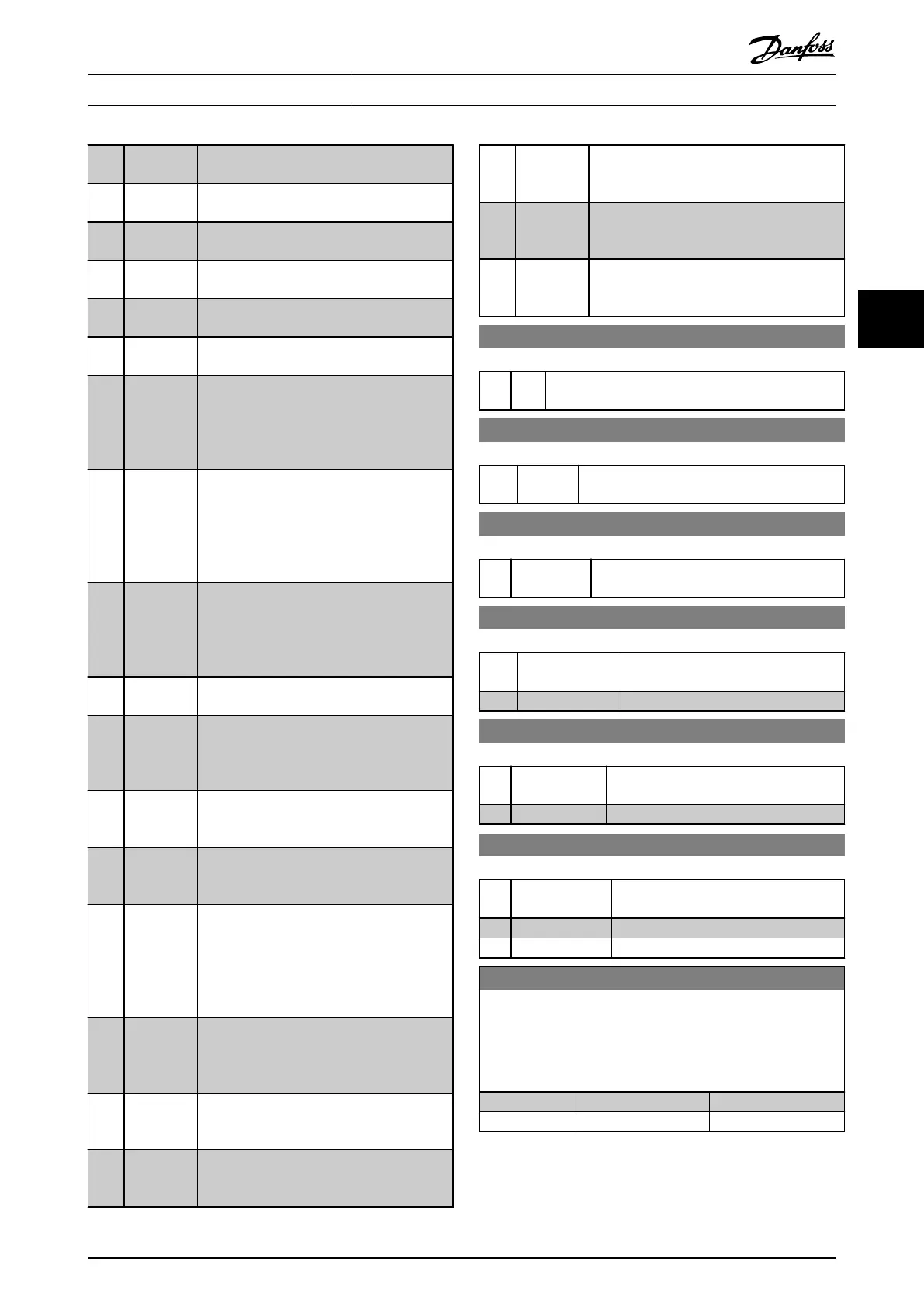
5-10 Terminal 18 Digital Input
Option: Function:
[8] * Start Functions are described in parameter group 5-1*
Digital Inputs.
5-11 Terminal 19 Digital Input
Option: Function:
[10] * Reversing Functions are described in parameter group
5-1* Digital Inputs.
5-12 Terminal 27 Digital Input
Option: Function:
[2] * Coast inverse Functions are described in parameter group
5-1* Digital Inputs.
5-13 Terminal 29 Digital Input
Option: Function:
[14] * Jog Functions are described in parameter
group 5-1* Digital Inputs.
[32] Pulse time based
5-14 Terminal 32 Digital Input
Option: Function:
[0] * No operation Functions are described in parameter
group 5-1* Digital Inputs.
[82] Encoder input B
5-15 Terminal 33 Digital Input
Option: Function:
[0] * No operation Functions are described in parameter
group 5-1* Digital Inputs.
[32] Pulse time based
[81] Enocder input A
5-19 Terminal 37/38 SAFE STOP
Use this parameter to set up the STO functionality. Warning
makes the frequency converter coast and enables automatic
restart. Alarm makes the frequency converter coast and requires
a manual restart.
Option: Function:
[1] * Safe Stop Alarm
[3] Safe Stop Warning
Parameter Descriptions Programming Guide
MG07C102 Danfoss A/S © 12/2015 All rights reserved. 53
4 4

 Loading...


