4.6.3 5-4* Relays
Parameters for conguring the timing and the output
functions for the relays.
The parameter is an array parameter showing 2 relays:
Array [2] (Relay 1 [0], Relay 2 [1]).
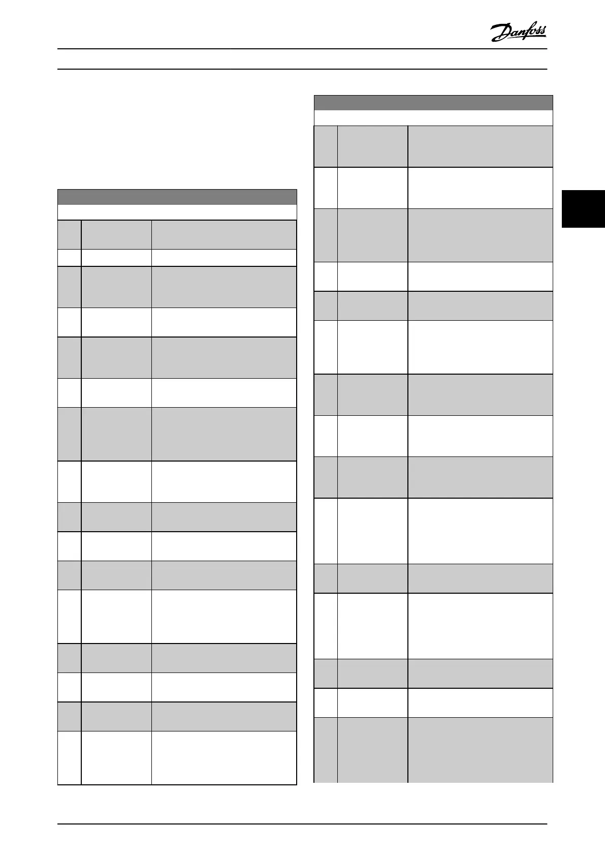
5-40 Function Relay
Option: Function:
[0] No operation Default setting for all digital and relay
outputs.
[1] Control Ready The control card is ready.
[2] Drive ready The frequency converter is ready to
operate. Mains and control supplies are
OK.
[3] Drive rdy/rem ctrl The frequency converter is ready for
operation, and is in auto-on mode.
[4] Stand-by / no
warning
Ready for operation. No start or stop
commands have been applied. No
warnings are active.
[5] Running The motor runs, and a shaft torque is
present.
[6] Running / no
warning
The output speed is higher than the
speed set in parameter 1-82 Min Speed
for Function at Stop [Hz]. The motor is
running and no warnings are present.
[7] Run in range/no
warn
The motor runs within the
programmed current ranges set in
parameter 4-50 Warning Current Low.
[8] Run on ref/no
warn
The motor runs at reference speed. No
warnings.
[9] Alarm An alarm activates the output. No
warnings.
[10] Alarm or warning An alarm or warning activates the
output.
[11] At torque limit The torque limit set in
parameter 4-16 Torque Limit Motor Mode
or parameter 4-17 Torque Limit
Generator Mode has been exceeded.
[12] Out of current
range
The motor current is outside the range
set in parameter 4-18 Current Limit.
[13] Below current,
low
The motor current is lower than set in
parameter 4-50 Warning Current Low.
[14] Above current,
high
The motor current is higher than set in
parameter 4-51 Warning Current High.
[15] Out of frequency
range
The output speed/frequency exceeds
the limit that is set in
parameter 4-40 Warning Freq. Low and
parameter 4-41 Warning Freq. High.
5-40 Function Relay
Option: Function:
[16] Below frequency,
low
The output frequency is lower than the
setting in parameter 4-40 Warning Freq.
Low.
[17] Above frequency,
high
The frequency is higher than the
setting in parameter 4-41 Warning Freq.
High.
[18] Out of feedb.
range
The feedback is outside the range set
in parameter 4-56 Warning Feedback
Low and parameter 4-57 Warning
Feedback High.
[19] Below feedback,
low
The feedback is below the limit set in
parameter 4-56 Warning Feedback Low.
[20] Above feedback,
high
The feedback is above the limit set in
parameter 4-57 Warning Feedback High.
[21] Thermal warning Thermal warning turns on when the
temperature exceeds the limit within
the motor, frequency converter, brake
resistor, or connected resistor.
[22] Ready, no thermal
warning
The frequency converter is ready for
operation, and there is no overtem-
perature warning.
[23] Remote,ready,no
TW
The frequency converter is ready for
operation and is in auto-on mode.
There is no overtemperature warning.
[24] Ready, no over-/
under voltage
The frequency converter is ready for
operation, and the mains voltage is
within the specied voltage range.
[25] Reverse The motor runs (or is ready to run)
clockwise when logic=0 and counter-
clockwise when logic=1. The output
changes when the reversing signal is
applied.
[26] Bus OK Active communication (no timeout) via
the serial communication port.
[27] Torque limit &
stop
Use for performing a coasted stop for
frequency converter in torque limit
condition. If the frequency converter
has received a stop signal and is in
torque limit, the signal is logic=0.
[28] Brake, no brake
warning
The brake is active, and there are no
warnings.
[29] Brake ready, no
fault
The brake is ready for operation, and
there are no faults.
[30] Brake fault (IGBT) The output is logic=1 when the brake
IGBT is short-circuited. Use this
function to protect the frequency
converter if there is a fault on the
brake module. Use the digital output/
Parameter Descriptions Programming Guide
MG07C102 Danfoss A/S © 12/2015 All rights reserved. 57
4 4

 Loading...


