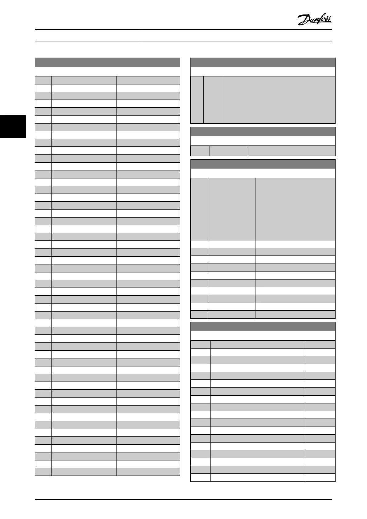
9-16 PCD Read Conguration
Option: Function:
[1613] Frequency
[1614] Motor current
[1615] Frequency [%]
[1616] Torque [Nm]
[1618] Motor Thermal
[1620] Motor Angle
[1622] Torque [%]
[1630] DC Link Voltage
[1633] Brake Energy /2 min
[1634] Heatsink Temp.
[1635] Inverter Thermal
[1638] SL Controller State
[1639] Control Card Temp.
[1650] External Reference
[1652] Feedback[Unit]
[1653] Digi Pot Reference
[1657] Feedback [RPM]
[1660] Digital Input
[1661] Terminal 53 Setting
[1662] Analog Input 53
[1663] Terminal 54 Setting
[1664] Analog Input AI54
[1665] Analog Output 42 [mA]
[1667] Pulse Input 29[Hz]
[1668] Pulse Input 33 [Hz]
[1669] Pulse Output 27 [Hz]
[1671] Relay Output
[1672] Counter A
[1673] Counter B
[1674] Prec. Stop Counter
[1684] Comm. Option STW
[1685] FC Port CTW 1
[1690] Alarm Word
[1691] Alarm Word 2
[1692] Warning Word
[1693] Warning Word 2
[1694] Ext. Status Word
[1695] Ext. Status Word 2
[1697] Alarm Word 3
[3421] PCD 1 Read For Application
[3422] PCD 2 Read For Application
[3423] PCD 3 Read For Application
[3424] PCD 4 Read For Application
[3425] PCD 5 Read For Application
[3426] PCD 6 Read For Application
[3427] PCD 7 Read For Application
[3428] PCD 8 Read For Application
[3429] PCD 9 Read For Application
[3430] PCD 10 Read For Application
[3450] Actual Position
[3456] Track Error
9-18 Node Address
Range: Function:
126* [ 0 -
126 ]
Enter the station address in this parameter or,
alternatively, in the hardware switch. To adjust the
station address in parameter 9-18 Node Address,
set the hardware switch to 126 or 127 (that is all
switches set to on). Otherwise, this parameter
shows the actual setting of the switch.
9-19 Drive Unit System Number
Range: Function:
1037* [0 - 65535 ] Manufacturer specic system ID.
9-22 Telegram Selection
Option: Function:
[1] Standard telegram 1 Select a standard PROFIBUS
telegram conguration for the
frequency converter as an
alternative to the freely cong-
urable telegrams in
parameter 9-15 PCD Write Congu-
ration and parameter 9-16 PCD Read
Conguration.
[100] * None
[101] PPO 1
[102] PPO 2
[103] PPO 3
[104] PPO 4
[105] PPO 5
[106] PPO 6
[107] PPO 7
[108] PPO 8
[200] Custom telegram 1
9-23 Parameters for Signals
Option: Function:
[0] *
[302] Minimum Reference
[303] Maximum Reference
[312] Catch up/slow Down Value
[341] Ramp 1 Ramp Up Time
[342] Ramp 1 Ramp Down Time
[351] Ramp 2 Ramp Up Time
[352] Ramp 2 Ramp Down Time
[380] Jog Ramp Time
[381] Quick Stop Ramp Time
[412] Motor Speed Low Limit [Hz]
[414] Motor Speed High Limit [Hz]
[416] Torque Limit Motor Mode
[417] Torque Limit Generator Mode
[553] Term. 29 High Ref./Feedb. Value
[558] Term. 33 High Ref./Feedb. Value
[590] Digital & Relay Bus Control
[593] Pulse Out 27 Bus Control
Parameter Descriptions
VLT
®
Midi Drive FC 280
76 Danfoss A/S © 12/2015 All rights reserved. MG07C102
44

 Loading...


