VLT
®
2800 Series
■ Dynamic braking
With the VLT 2800 the d ynamic braking quality in an
application can be improved in two ways, either w ith
the aid of brake resistors or AC braking.
Danfoss offers a complete range of brake resistors
for all VLT 2800 freque ncy converters.
It is the job of the brake resistor to apply a
load to the intermediate circuit during braking,
thereby ensuring that the brake pow er can be
absorbed by the brake resistor.
Without a brake resistor, the intermediate circuit
voltage of the frequency converter would go on rising,
until cutting o ut for protection. The advantage of
using a brake resistor is that you can brake quickly
with large loads, e.g. on a conveyor belt.
Danfoss has chosen a solution in which the brake
resistor is not integrated into the frequency con verter.
This gives the user the following advantages:
-Theresistor’s cycle time can be selected as required.
- The heat generated d uring braking ca n be
diverted outside the panel cabinet, where the
energy can possibly be ut ilised.
- No overheating of the electronic components,
even if the brake resistor is overloaded.
AC braking is an integrated functio n that is used
for applications in which there is a ne ed for lim ited
dynamic braking. The AC braking function ma kes
it possible to reduce the brake power in the motor
instead of in a brake resistor. The function is intended
for applications where the required braking torque
is less than 50% of rated torque. AC braking is
selected in par. 400 Brake function.
NB!:
The AC brake cannot be used if the
required braking torque is m ore than 50%
of rated braking torque. In such instances
a brake resistor must be used.
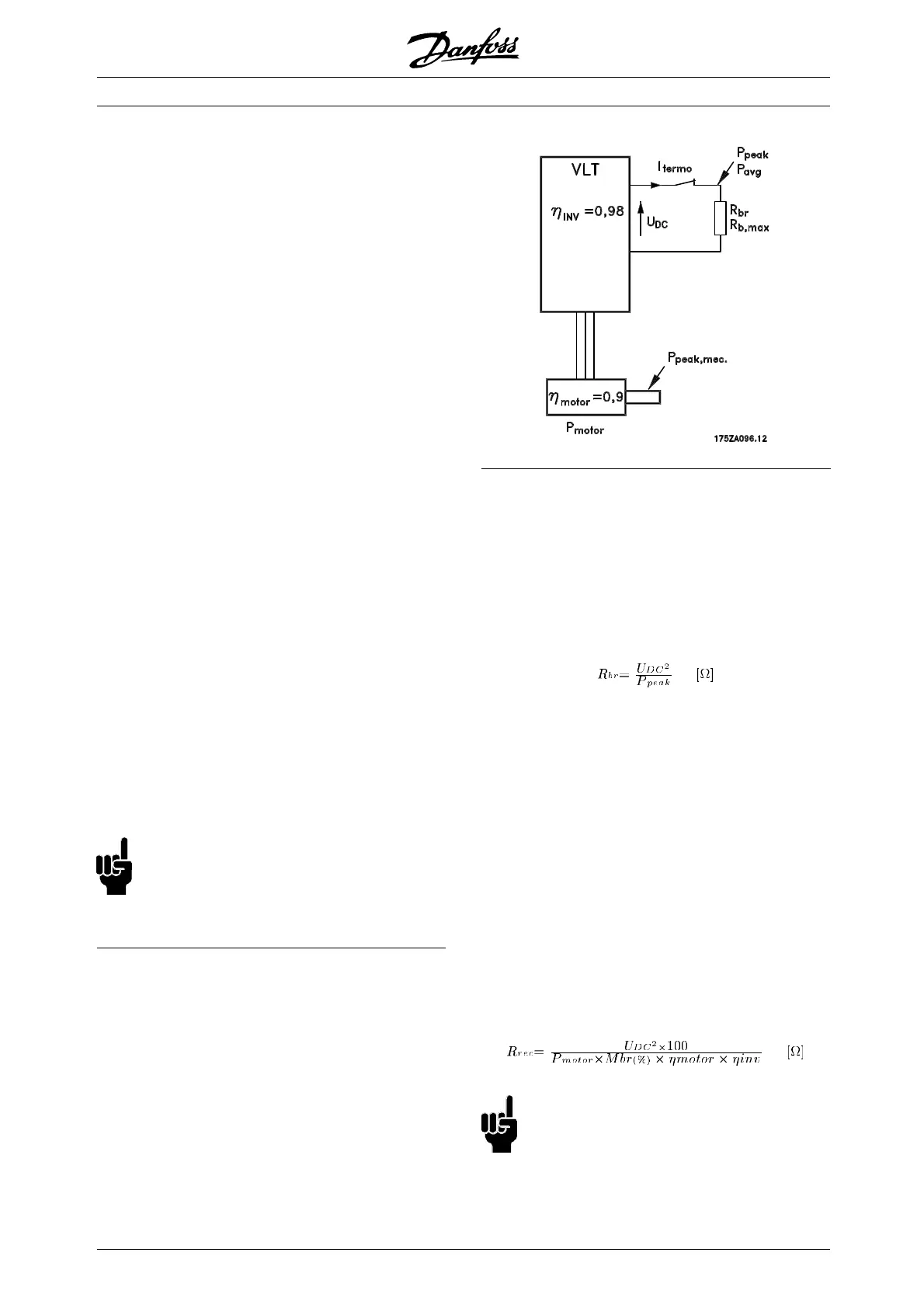
■ Brake Setup
ThefigureshowsabrakeSetupwitha
frequency converter.
In the following paragraphs, expressions and
acronyms are used about brake Setups that
can be seen from the figure.
■ Calculation of brake resistance
The following example and formula only apply
to VLT 2800 Series.
To ensure that the frequency converter does not cut
out for safety reasons when the motor b rakes, the
resistance value is selected on the basis of the peak
braking effect and the intermediate circuit voltage:
It can be seen that the brake resistance depends
on the intermediate circuit voltage (UDC).
With frequency converters that have a mains voltage
of 3 x 380 - 480 Volt, the brake will be act ive at
770 Volt (UDC); if the frequency converter has a
mains voltage of 3 x 200 - 240 Volt, the brake
will be active at 385 Volt (UDC).
You c an also choose to use the brake resistance
recommended by Danfoss (R
REC
). This is a
guarantee that the frequency conve rter
is able to
brakeatthehighestbrakingtorque(M
BR
). The
recommended brake resistance can be seen from
the ordering table for brake resi
stors.
R
REC
calculated as:
NB!:
Remember to check that the brake resistance
can manage a voltage of 850 Volt or 430 Volt,
if Danfoss brake resistors are not being used.
MG.28.E9.02 - VLT is a registered Danfoss trademark
24
 Loading...


