VLT
®
2800 Series
Programming
Lowpass filter
If there is a lot of noise in the feedback signal, these
can be dampened using an integrated lowpass filter.
A suitable l owpass filter t ime constant is preset.
If the lowpass filter is preset to 0.1 s, the cut-off
frequency will be 10 RAD/sec, corresponding to (10 / 2
x π) = 1.6 Hz. Th is will mean that all currents/voltages
that vary by more than 1.6 oscillations per second
will be dampened. In other words, there will only
be regulation on the basis of a fe edback signal
that varies by a frequency of less than 1.6 Hz.
The appropriate time constant is selected in Speed
Regulation in parameter 421 Speed PID lowpass
filter time and in Proces s Regulation in parameter
444 Process PID lowpass filter time.
I
nverse reg ulation
Normal regulati on means that the motor speed is
increased when the reference/setpoint is greater
than the feedback signal. If it is necessary to run
inverse regulation, in which the speed is reduced
when the reference/setpoint is greater than the
feedback signal, parameter 437 PID normal/inverted
control must be programmed at Inverted .
A
nti Windup
In the factory the process regulator is preset with
an act ive anti windup function. This function means
that when either a frequency limit, a current limit or
a voltage limit is rea ched, the integrator is initialised
at a frequency corres ponding to the present output
frequency. This is a m eans o f avoiding the integration
of a variance between the reference and the process’s
actual mode that cannot be deregulated by means of
a change of speed. This function can be deselected
in parameter 438 Process PID anti windup.
S
tarting conditions
In some applications the optimal setting of the
process regulator will mean that a relatively long
period of time will pass befo re the required process
condition is achieved. In these applications it can
be a good idea to define an output frequency to
which the frequency converter must run the motor
before the process regulator is activated. This is
done by programming a start frequency in parameter
439 Process PID start frequ ency.
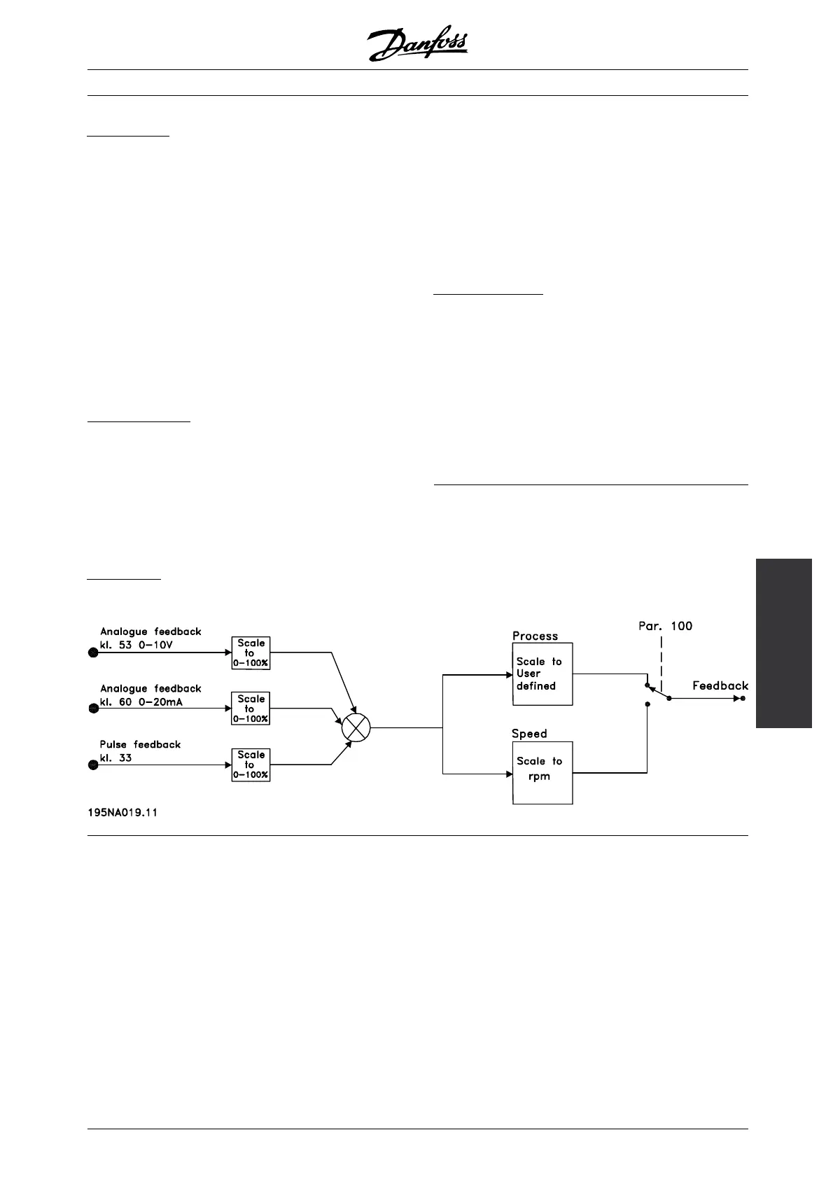
■ Handling of feedback
Feedback handling is depicted in this flowchart.
The flowchart shows which parameters can a ffect the
handling of feedback and how. A choice can be made
between voltage, current and pulse feedback signals.
✭ = factory setting. () = di splay text [] = value for use in communication via serial communicat ion port
MG.28.E9.02 - VLT is a registered Danfoss trademark
101
 Loading...


