VLT
®
2800 Series
This table shows what the output frequency is:
Preset
ref., msb
Preset
ref., lsb
Selection
of Setup
Output
frequency[Hz]
0 0 0 2.5
0 1 0 5
1 0 0 10
1 1 0 17.5
0 0 1 20
0 1 1 25
1 0 1 35
1 1 1 50
■ Connection of mechanical brake
Use of the relay for 230V AC brake
Par. 302 Digital input = Start [7]
Par. 304 Digital input = Coast ing stop inverted [2]
Par. 323 Re lay output = Mechanical
brake control [25]
Mechanical brake control [25] = ’0’ => Brake is closed.
Mechanical brake control [25] = ’1’ => The
brake is open.
See more detailed parameter settings under
Control of mechanical brake .
NB!:
Do not use the internal relay for DC brakes
or brake voltages > 250 V.
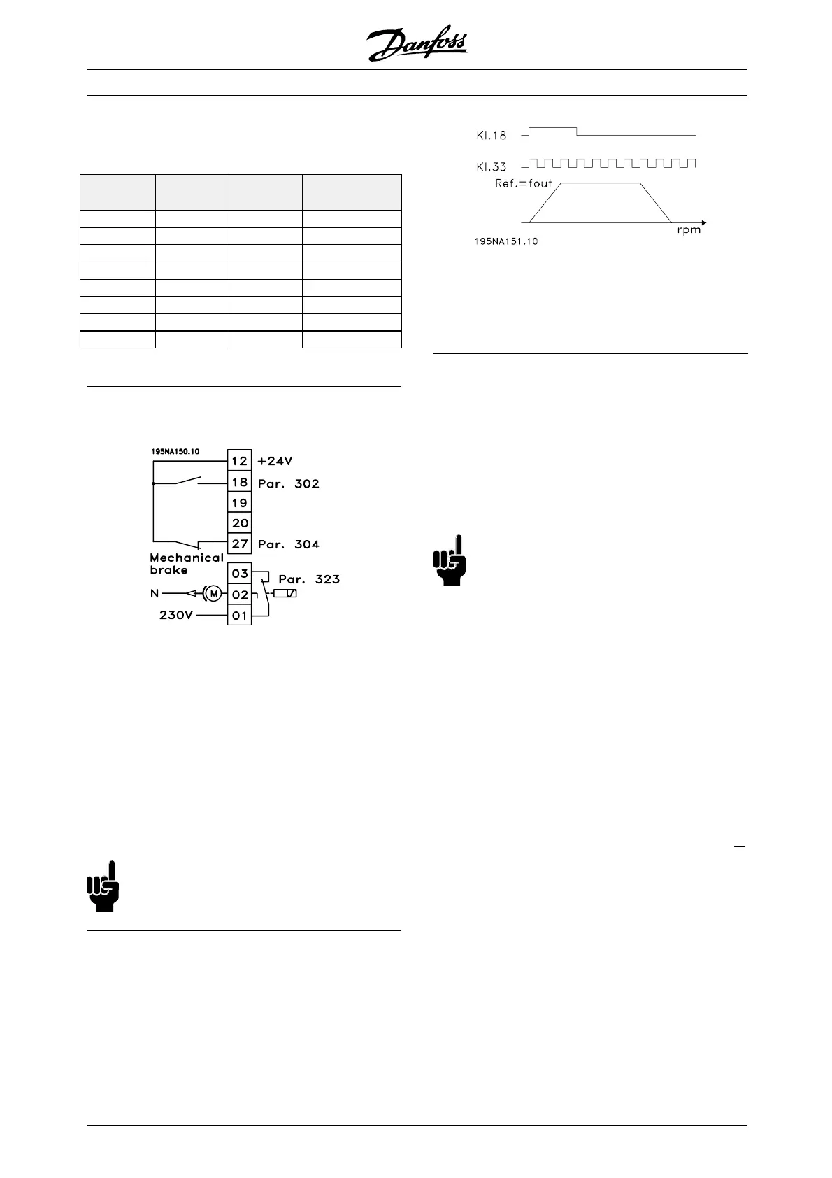
■ Counter stop via terminal 33
The start signal (terminal 18) must be active, i.e. logical
’1’, until the output frequency is equal to the reference.
The start signal (terminal 18 = logical ’0’) must then be
removed before the counter value in parameter 344
has managed to stop the VLT frequency converter.
Par. 307 Digital input = Pulse input [30]
Par. 343 Precise stop function = Counter
stop with reset [1]
Par. 344 Counter value = 100000
■ Use of internal PID-controller - closed
loop process control
1. Connect the frequency converter to mains
and motor cables as usual.
2. Connect transmitter (feedback signal) to + terminal
12 and - terminal 60 (applies to 2-wire transmitters
4-20 mA). (Connect transmitters with 0-10 V DC
to + terminal 53 and - terminal 55).
NB!:
Connect terminal 55 as - and terminal 60
as + for current signal (0/4-20 mA) and
terminal 53-55 for voltage signal (0-10 V DC) if
transmitters with separate voltage supply a re used.
3. Connect the start signal between terminal 1 2
and 18, 12-27 must be connected or set to
no function (parameter 304 = 0).
4. Set all parameters in the Quick M enu and enter
the Main Menu (to enter the Main Me nu: Press
Quick Menu and + simultaneously).
5. Set the following parameters:
100 = Proc ess controller closed loop [3]
101 = Variable torque medium [3]
If used with centrifugal pumps and fans.
308 = Feedback [2] (for 0-10 V DC transmitters) o
r
314 = Fe edback [2] (for 4-20 mA transmitters)
414 = Minimum feedback scaling, must be set
to the minimum feedb ack value
415 = Ma ximum feedba ck scaling, must be set
to the maximum feedback value
Example: Pressure transmitter 0-10 bar:
414 = 0 and 415 = 10
416 = Proce ss units: As shown on the local
control panel (example: bar [4])
437 = Normal [0]: The output frequency should be
reduced when the feedback signal increases
Inverse [1]: The output frequency should increase
when the feedback signal increases
440 = Proport ional gain (P-gain) 0.3-1.0
(experienced value)
MG.28.E9.02 - VLT is a registered Danfoss trademark
58
 Loading...


