VLT
®
2800 Series
Programming
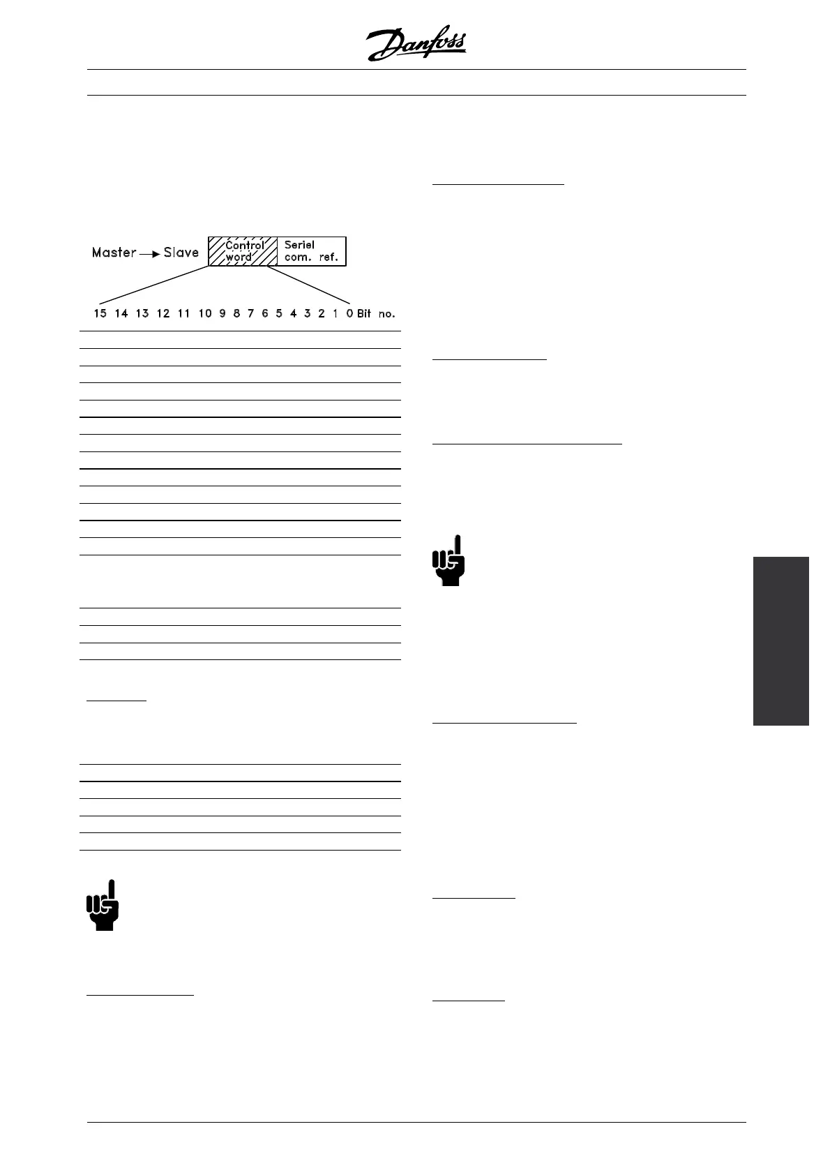
■ Control Word according to FC protocol
To select FC protocol in the control word, parameter
512 Telegram Profile must be set to FC protocol [1].
The control word is used to send commands from a
master ( e .g. a PC) to a slave ( frequency converter).
Bit B it = 0 Bit =1
00 Preset ref. lsb
01 Preset ref. msb
02 DC braking
03 Coasting stop
04 Quick stop
05 Freeze outp. freq.
06 Ramp stop Start
07 Reset
08 Jog
09 Ramp 1 Ramp 2
10 Data not valid Data valid
11 No funct i on Relay 01 activated
12 No function D igital output
Terminal 46
activated
13 Select Setup, lsb
14 Select Setup, msb
15 Reversing
Bit 00/01:
Bit 00/01 is used to select between the two
pre-programmed references (parameters 215-218
Preset reference) according to the following table:
Preset ref. Parameter Bit 01 Bit 00
121500
221601
321710
421811
NB!:
In parameter 508 Select ion of preset
reference a selection is made to define how
Bit 00/01 gates with the corresponding
function on the digital inputs.
B
it 02, DC brake:
Bit 02 = ’0’ ca uses DC braking and stop. Brake
voltage and durati on are preset in parameters
132 DC brake voltage and parameter 126 DC
braking t ime. Note: In parameter 504 DC brake a
selection is made to define how Bit 02 gates with
the corresponding function on a digital input.
B
it 03, Coasting stop:
Bit 03 = ’0’ causes the frequency converter to
immediately "let go" of the motor (the output transistors
are "shut off"), so that it coasts to a standstill.
Bit 03 = ’1’ causes the frequency converter to be able
start the motor if the other starting conditions ha ve
been fulfilled . Note: In parameter 502 Coast i ng stop
a selection is made to define how Bit 03 gates with
the corresponding function on a digital input.
B
it 04, Q uick stop:
Bit 04 = ’0’ causes a stop, in which the motor’s
speedisrampeddowntostopviaparameter
212 Quick stop ramp-down time.
B
it 05, Freeze outp ut frequency:
Bit 05 = ’0’ causes the present output frequency
(in Hz) to freeze. The frozen output frequency can
now only be changed by means of the digital inputs
programmed to Speed up and Speed dow n.
NB!:
If Freeze output is active, the frequency
converter cannot be s topped v ia Bit 06 Start
or via a digital input. The frequency converter
can only be stopped by the following:
• Bit03Coastingstop
• Bit 02 DC braking
• Digital input programmed to DC braking, Coasting
stop or Reset and coasting stop.
B
it 06, Ramp stop/start:
Bit 06 = ’0’ causes a stop, in which the motor’s
speed is ramped down to stop via the selected
ramp down parameter.
Bit 06 = ’1’ causes the frequency converter to be able
to start the motor, if the other starting conditions h ave
been fulfilled. Note: In parameter 505 Start a selection
is made to define how Bit 06 Ramp stop/start gates
with the corresponding function on a digital input.
B
it 07, Reset:
Bit 07 = ’0’ does not cause a reset.
Bit 07 = ’1’ causes the reset of a trip. Reset is
activated on the signal’s leading edge, i.e. when
changing from logic ’0’ to logic ’1’.
B
it 08, Jog:
Bit 08 = ’1’ causes the output frequency to be
determined by parameter 213 Jog frequency.
MG.28.E9.02 - VLT is a registered Danfoss trademark
113
 Loading...


