VLT
®
2800 Series
Introduction to VLT
2800
■ Display readout states
Display mode
In normal operation, one item of operating data can
be displayed continuously at the operator’sown
choice. By means of the [+/-] keys the following
options c an be sele cted in Display mode :
-Outputfrequency[Hz]
- Output current [A]
-Outputvoltage[V]
- Intermediate circuit voltage [V]
-Outputpower[kW]
- Scaled output frequency f
out
x p008
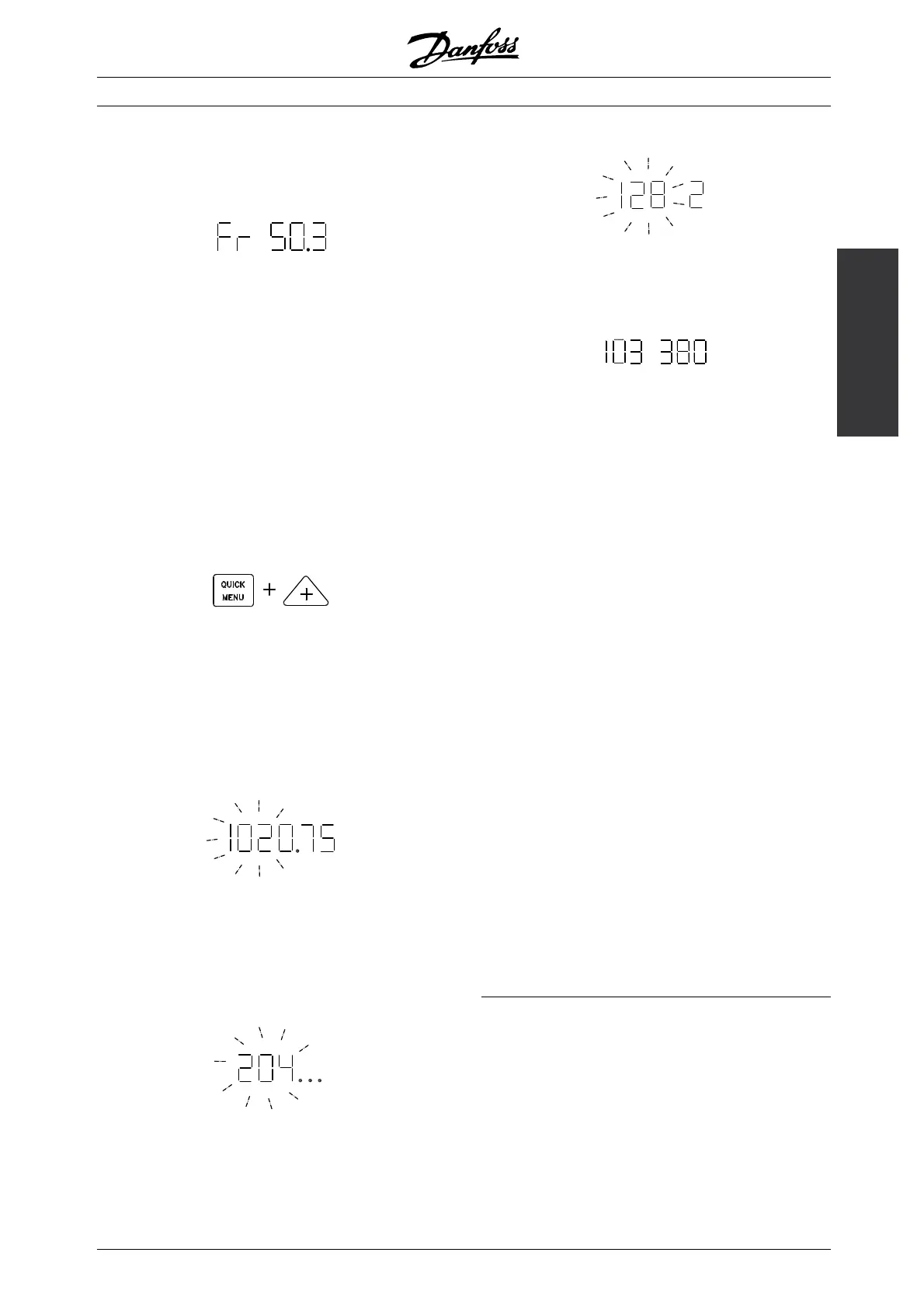
Menu mode
In order to enter the Menu mode [QUICK MENU]
+ [+] must be act ivated at the same time.
In Menu mode, most of the frequency converter
parameters can be changed. Scroll through the
parameters using the [+/-] keys. W h ile scrolling in the
Menu mode proceeds, the parameter number will flash.
The display shows that the setting in parameter
102 Motor power P
M,N
is 0.75. In order to change
the value of 0.75, [CHANGE DATA] must first
be activated; the parameter value can then be
changed using the [+/-] keys.
If for a given p arameter the display shows three
dots at the right, it means that the parameter
value has more than three digits. In order to see
the value, activate [CHAN GE DATA].
The display shows that in parameter 128 Motor thermal
protection the selection made is Thermistor trip [2].
Quick menu
Using the [QU ICK MENU] key, it is possible to access
the 1 2 most important parameters of the frequency
converter. After programming, the frequency converter
is in mos t cases ready for operation. When the
[QUICK M ENU] key is activated in Display mode, the
Quick menu starts. Scroll through the quick menu
using the [+/-] keys and change the data value s by
first pressing [CHANGE DATA] and then changing
the parameter value with the [+/-] keys.
The Q uick menu parameters are:
• Par. 100 Configuration
• Par. 101 Torque characteristic
• Par. 102 Motor power P
M,N
• Par. 103 Motor voltage U
M,N
• Par. 104 Motor frequency f
M,N
• Par. 105 Motor current I
M,N
• Par. 106 Rated motor speed n
M,N
• Par. 107 Automatic motor adaptation
• Par. 202 Output frequency high limit f
MAX
• Par. 203 Reference range
• Par. 204 Minimum reference Ref
MIN
• Par. 205 Maximum reference Ref
MAX
• Par. 207 Ramp-up time
• Par. 208 Ramp-down tim e
• Par. 002 Local/remote operation
• Par. 003 Local reference
Parameter 102 - 106 can be read out from
the motor’s nameplate.
■ Hand Auto
During normal operation the frequency converter is
in Auto mode, whe re the reference signal is given
externally, analog or digital via the control terminals.
However, in Hand mode, it is possible to give the
reference signal locally via the control panel.
MG.28.E9.02 - VLT is a registered Danfoss trademark
31
 Loading...


