VLT
®
2800 Series
Bit 09, Selection of ramp 1/2:
Bit 09 = "0" means that ramp 1 is active (parameters
207/208). Bit 09 = "1" means that ramp 2
(parameters 209/210) is act ive.
B
it 10, Data not valid/Data valid:
Is used to tell the frequency converter w hether the
control word is to be used or ignored. Bit 10 =
’0’ causes the control word to be ignored, Bit 10
= ’1’ causes the control word to be used. This
function is relevant, because the control w ord is
always contained in the telegram, regardless o f which
type of telegram is used, i.e. it is possible to turn
off the control word if you do not wish to use it in
connection with updating or reading parameters.
B
it 11, Relay 01:
Bit 11 = "0" Relay not activ ated.
Bit 11 = "1" Relay 01 a ct ivated, provided Control
word bit has b ee n chosen in pa rame ter 323.
B
it 12, Digital ou tput, terminal 46:
Bit 12 = "0" Digital output has not been activated.
Bit 12 = "1" Digital output has bee n activated, provided
Control word bit ha s been chosen in parameter 341.
B
it 13/14, Select ion of Setup:
Bits 13 and 14 are used to choose from the four
menu Setups according to the following table:
Setup Bit 14 Bit 13
100
201
310
411
The function is only possible when Multi-Setups is
selected in parameter 004 Active Setup .
Note: I par
ameter 507 Se lection of Se tup a selection
is made to define how Bit 13/14 gates with the
corresponding function on the digital inputs.
B
it 15 Reversing:
Bit 15 = ’
0’ causes no reversing.
Bit 1 5 = ’1’ causes reversing.
Note: In the factory setting reversing is set to
digital
in parameter 506 Reversing. Bit 15 only
causes reversing when either Ser. communication
, Logic or or Logic and is selected.
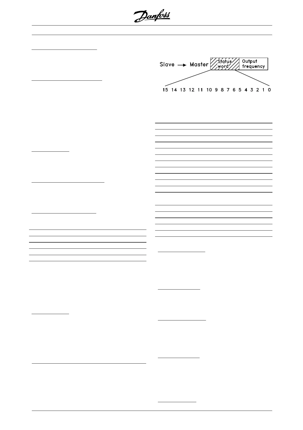
■ Status Word according to FC Profile
The status word is used to inform the master
(e.g. a PC) of the slave’s (frequency converter)
mode. Slave⇒Master.
Bit Bit = 0 Bit =1
00 Control ready
01 Drive ready
02 Coasting stop
03 No trip Trip
04 Not used
05 Not used
06 Trip lock
07 No warning Warning
08 Speed ≠ ref. Speed = ref.
09 Local control Ser. communi.
10 Outside
frequency range
Frequency limit
OK
11 Motor running
12
13 Voltage warn.
14 Current limit
15 Thermal warn.
Bit 00, Control ready:
Bit 00 = ’1’. The frequency converter is
ready for operation.
Bit 00 = ’0’. The frequency converter is
not ready for operation.
B
it 01, Drive ready:
Bit 01 = ’1’. The frequency converter is ready for
operation, but there is an active coasting command
via the digital inputs or via serial communication.
B
it 02, Coasting stop:
Bit 02 = ’0’. The frequency converter has
released the motor.
Bit 02 = ’1’. The frequency converter can start the
motor when a start command is given.
B
it 03, No trip/trip:
Bit 03 = ’0’ means that the frequency converter
is not in fault mode.
Bit 03 = ’1’ means that the frequency converter
is tripped, and that it needs a reset signal for
operation to be reestablished.
B
it 04, Not used:
Bit 04 is not used in the status word.
MG.28.E9.02 - VLT is a registered Danfoss trademark
114
 Loading...


