VLT
®
2800 Series
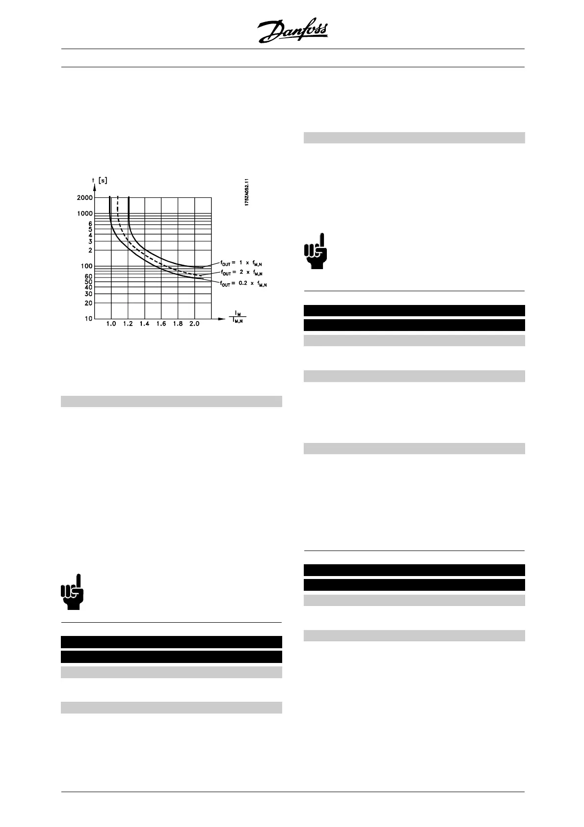
- Thermal load calculat ion ( ETR - Electronic
Thermal Relay), based on present load and
time. T his is compared with the rated motor
current I
M,N
and rated motor frequency f
M,N
.
The calculations take into account the ne ed for
lower loading at low speeds due to the motor’s
internal ventilation being reduced.
ETR functions 1-4 do not begin to calculate the load
until you switch to the Se tup in which they have been
selected. This means that you can use the ETR function
even when changing between two or more motors.
Description of choice:
Select No protection [0] if you do not want a warning
or trip when a motor is overloaded.
Select Thermistor warning [1] if you want a w arning
when the connec ted thermistor becomes too hot.
Select Thermistor trip [2] if you want a trip when
the
connected thermistor becomes too ho t.
Select ETR w arning 1-4 if you want a w arning when
the m otor is overloaded according to the calcul
ations.
You can also programme the f requency converter to
give a warning signal via one of the digital outputs.
Select ETR Trip 1-4 if you w ant a trip whe
nthemotor
is overloaded according to the calculatio ns.
NB!:
This function cannot protect the individual
motors in the case of motors linked i
n p arallel.
130 Start frequency
(START FREQUENCY)
Value:
0.0 - 10.0 Hz
✭ 0.0 Hz
Function:
Thestartfrequencyisactiveforthetimesetin
parameter 120 Start delay, after a start command.
The output frequency will ’jump’ tothenextpreset
frequency. Certain motors, such as conical anchor
motors, need an extra voltage/start frequency
(boost) at start to disengage the mechanical brake.
To achieve this parameters 130 Start frequency
and 131 Initial voltage are used.
Description of choice:
Set the required start freque ncy. It is a precondition
that parameter 121 Start function,issetto
Start frequency/voltage clockwise [3] or Start
frequency voltage in reference direction [4] a nd
that in parameter 120 Start delay atimeisset
and a reference signal is p resent.
NB!:
If parameter 123 is set higher than parameter
130, the start dela y function ( p arameter
120 and 121) will be skipped.
131 Initial voltage
(INITIAL VOLTAGE)
Value:
0.0 - 200.0 V
✭ 0.0 V
Function:
Initial voltage is active for the time set in parameter
120 Start delay , after a start command. This
parameter can be used for example for lifting/dropping
applications (conical anchor motors).
Description of choice:
Set the required voltage necessary to cut out the
mechanical brake. It is assumed that parameter
121 Start function,issettoStart frequency/voltage
clockwise [3] or Start frequ ency/voltage in refere nce
direction [4] and that in parameter 120 Start delay a
time is set, and that a reference signal is present.
132 DC brake voltage
(DC BRAKE VOLTAGE)
Value:
0 - 100% of max. DC brake voltage
✭ 0%
Function:
In this parameter, the D C brake voltage is set which is
to be activated at stop when the DC brake frequency
set in parameter 127 DC brake cut-in frequency is
reached, or if DC braking inverse isactiveviaadigital
input or via serial co mmunication. Subsequently,
the DC brake voltage will be active for the time
set in parameter 126 DC brake t ime.
✭
= factory setting. () = display text [] = value for use in communication via serial communication port
MG.28.E9.02 - VLT is a registered Danfoss trademark
74
 Loading...


