Application guidelines
82 FRCC.PC.023.A7.22
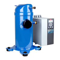
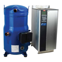
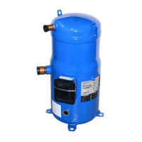
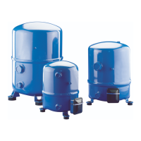
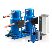
Manifold compressors
System design recommendation
Cycle rate limit of SH
compressors
The system must be designed in a way that
guarantees a minimum compressor running
time of 3 minutes so as to provide for sucient
motor cooling after start-up along with proper oil
return. Note that the oil return may vary since it
depends upon system design. There must be no
more than 12 starts per hour; a number higher
than 12 reduces the service life of the motor
compressor unit. If necessary, place an anti-short-
cycle timer in the control circuit, connected as
shown in the wiring diagram in the Danfoss SH
scroll compressors application guidelines. A
4-minute timeout is recommended.
Short cycle control is directly provided by the
CDS303 frequency converter, when parameter
28.0x is enabled. The function is factory set to
enabled, with minimum running time 12 seconds
and interval between starts 300 seconds. Short
cycle settings are accessible in parameter 28.0x
list, in the compressor functions” menu.
If the evaporator lies above the compressor, as
is often the case in split or remote condenser
systems, the addition of a pump-down cycle is
strongly recommended. If a pump-down cycle is
omitted, the suction line should have a loop at
the evaporator outlet to prevent refrigerant from
draining into the compressor during o-cycles.
If the evaporator was situated below the
compressors, the suction riser must be trapped
so as to prevent liquid refrigerant from collecting
at the thermal bulb location.
When the condenser is mounted at a higher
position than the compressors, a suitably sized
“U”-shaped trap close to the compressors is
necessary to prevent oil leaving the compressor
from draining back to the discharge side of the
compressors during o cycle. The upper loop also
helps avoid liquid refrigerant from draining back
to the compressor when stopped.
Piping should be designed with adequate three-
dimensional exibility. It should not be in contact
with the surrounding structure, unless a proper
tubing mount has been installed. This protection
proves necessary to avoid excess vibration, which
can ultimately result in connection or tube failure
due to fatigue or wear from abrasion. Aside from
tubing and connection damage, excess vibration
may be transmitted to the surrounding structure
and generate an unacceptable noise level within
that structure as well (for more information on
noise and vibration, see section “Sound and
vibration management” in Danfoss SH scroll
compressors application guidelines).
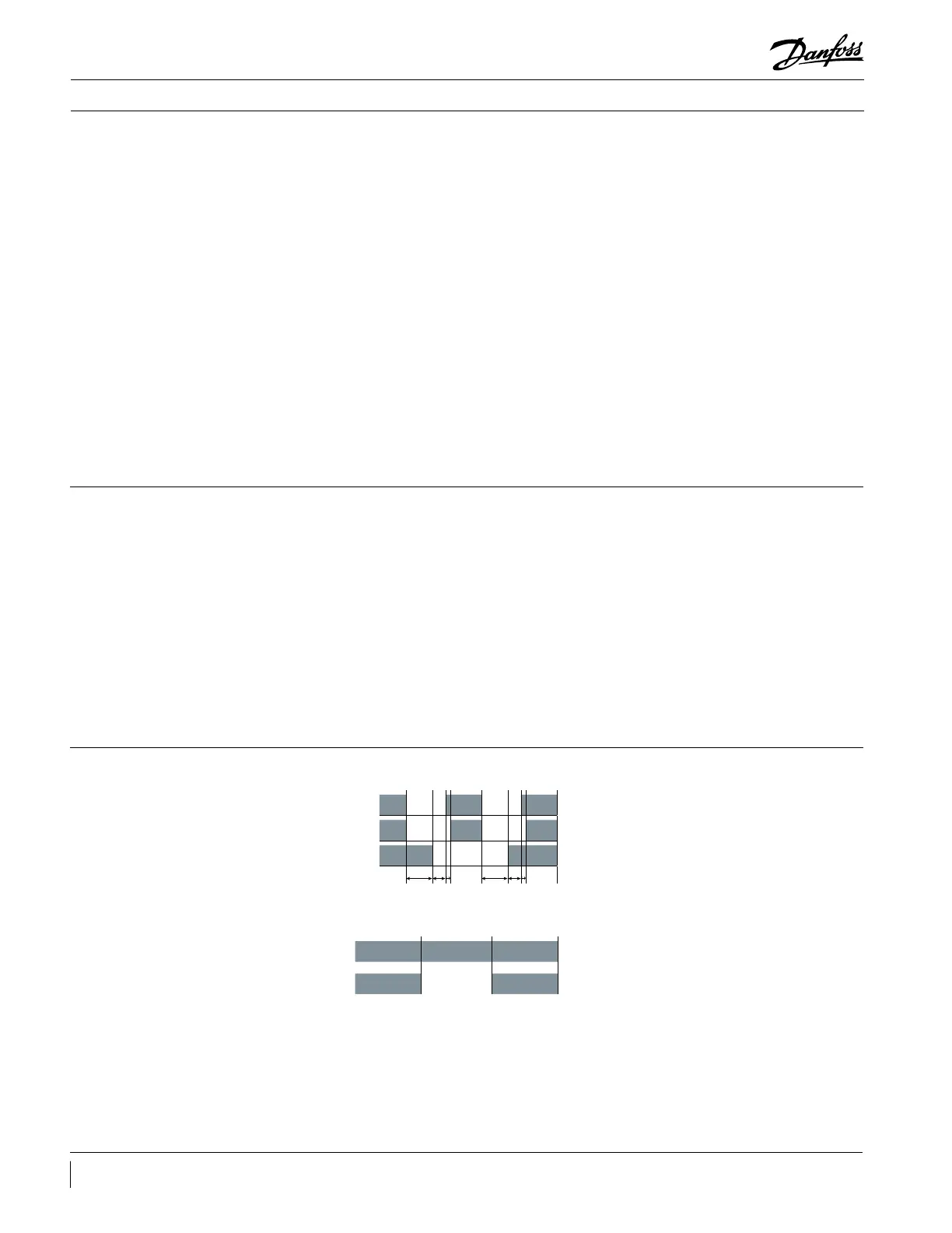
Defrost cycle logic
Start of defrost
sequence
End of defrost
sequence
Compressor 1 on
Compressor 1 o
Compressor 2 on
Compressor 2 o
4 way valve position 1
4 way valve position 2
10" 2" 10" 2"
Start of defrost
sequence
End of defrost
sequence
Compressors on
Compressors o
4 way valve 1
4 way valve 2
In order to limit liquid amount handled per
compressor when beginning & ending defrost,
one of the 2 defrost cycle logics are required:
y stop all compressors before moving the
4way valve:
rst stop compressors
wait for 10 seconds
move the 4 way valve
wait for 2 seconds
restart the compressors with a max. 0.5
second delay between 2 successive starts
or
y keep all compressors running during defrost
cycle
Defrost cycle logic must respect all system
components recommendations, in particular 4
way valve Max. Operating Pressure Dierential.
EXV can also be opened when compressors are
stopped and before 4 way valve is moving in
order to decrease pressure dierence. Opening
degree and time have to be set in order to keep
a minimum pressure for 4 way vavle moving.
Danfoss recommend above two defrost cycle
logic, but the control logic is also system
specied.
0.5" 0.5"
 Loading...