88
Analog Module
Micro-Switch Settings
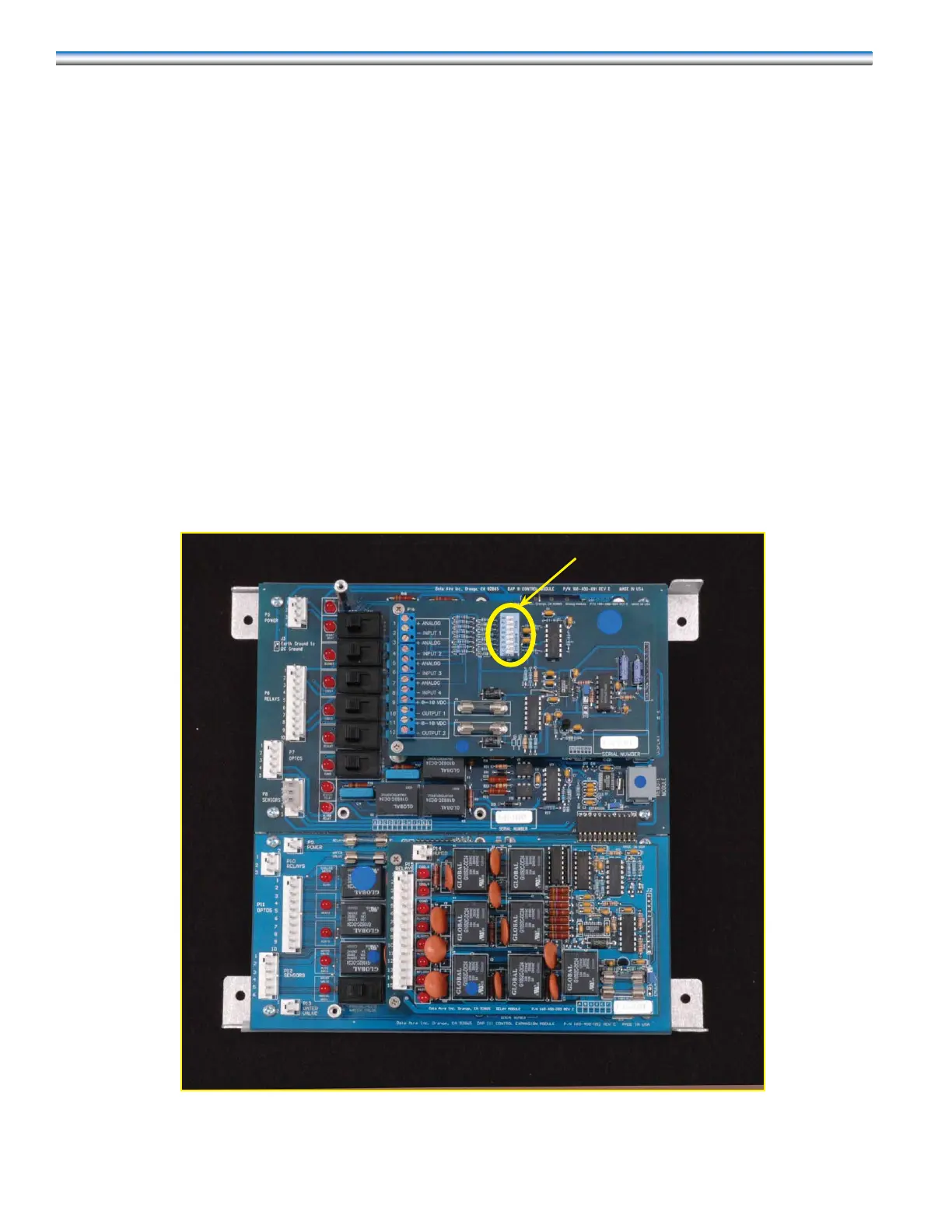
On the Analog Module there is a set of eight micro switches that must be set in conjunction with sub-menu 10-3
to establish signal range. Below is a photo of the Analog Module with the switches circled in yellow. Also a table indi-
cating the appropriate settings for the various input options.
Input 1: Switch 1 Switch 2 Input 3 Switch 5 Switch 6
0-5 v OFF OFF 0-5 v OFF OFF
0-10 v OFF ON 0-10 V OFF ON
4-20 mA ON OFF 4-20 mA ON OFF
Input 2: Switch 3 Switch 4 Input 4 Switch 7 Switch 8
0-5 v OFF OFF 0-5 v OFF OFF
0-10 v OFF ON 0-10 v OFF ON
4-20 mA ON OFF 4-20 mA ON OFF
Micro-switches