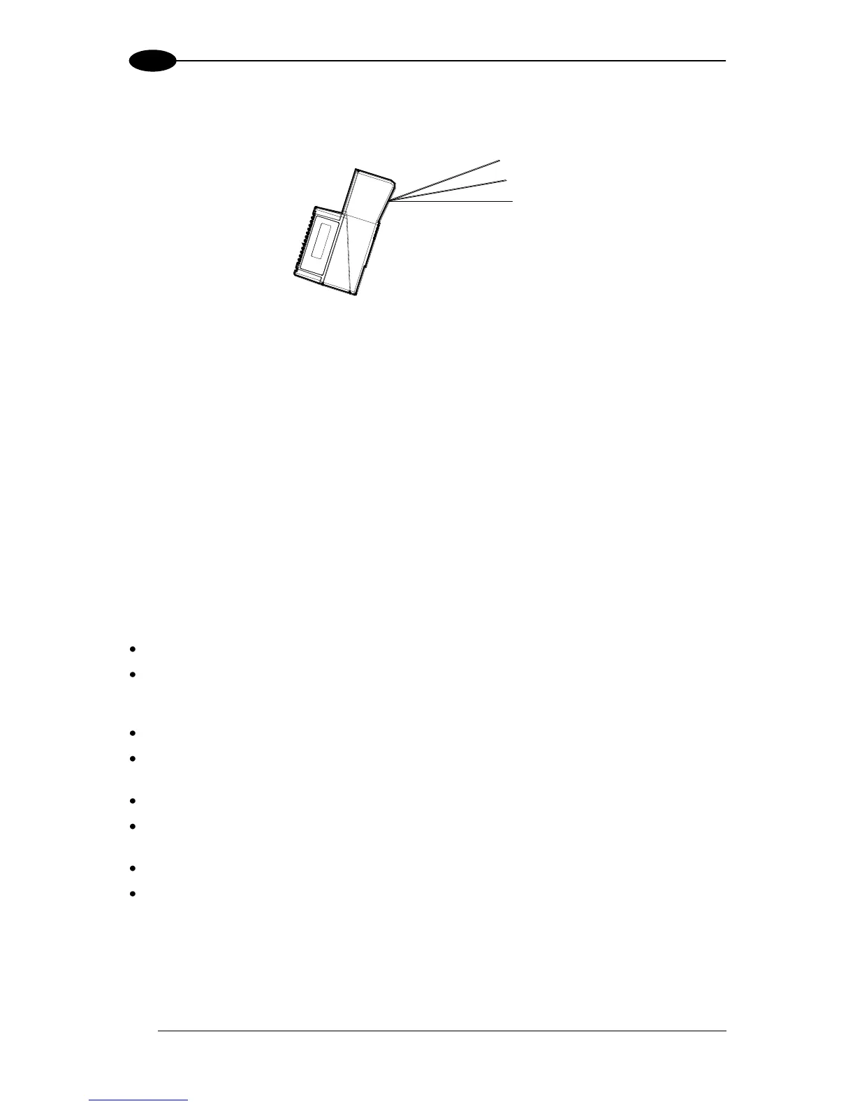
The following example represents the selection of an angle of +10° for the bottom line and an
angle of +20° for the top line (see figure below).
Figure 5 - Oscillating Mode
Refer to chapter 2 for more information on scanner mounting and positioning.
1.5 INDICATORS
The DS6400 has three LEDs on the Display and Keypad panel. The indicators have the
following functions:
1.6 KEYPAD AND DISPLAY
The DS6400 keypad allows entering a menu for selection of one of the following functions:
Welcome: shows the current software release and operating mode;
Autolearn: starts the procedure making it possible to obtain an automatic, accurate
and fast configuration of DS6400 without the necessity of directly
checking/modifying the relevant parameters;
Internal Net: defines scanner function within the local Lonworks network (see below);
Ethernet Mode: allows setting the scanner IP address of the Master scanner to be used
within the Host network;
LCD Contrast: sets the LCD contrast;
Bus: allows setting the scanner address (value range 0-125) to be used in a
Profibus network;
Test Mode: allows verifying the scanner reading position and features (see below).
PackTrack: allows setting the Auto PackTrack Calibration procedure (see below).
The same settings may be performed by using the Genius™ program (see chapter 8 for
details).