When using DeviceNet, the Main serial interface is disabled and must not
be physically connected.
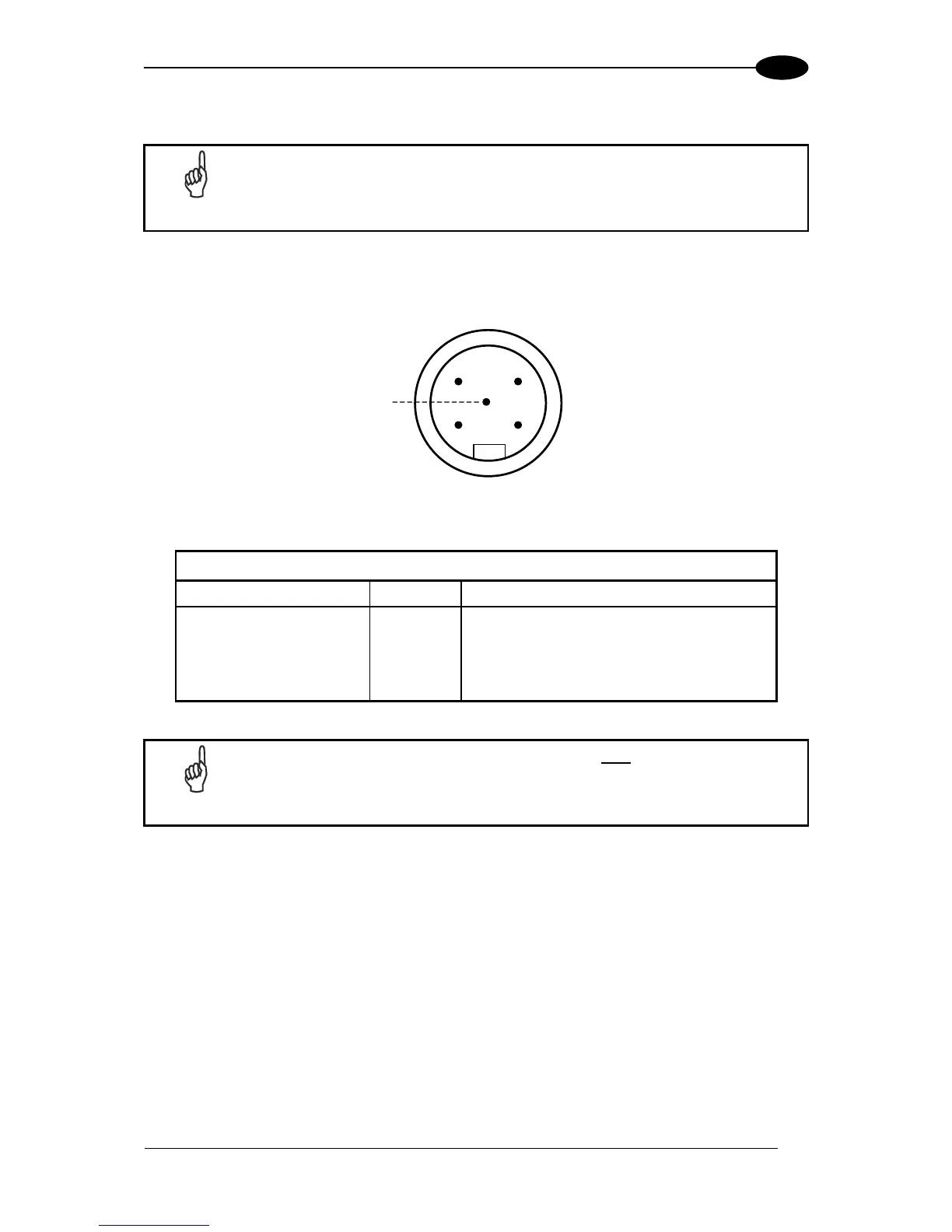
The 5-pin male connector is only available in the DS6400 DeviceNet model and allows
connection between the host and the reader:
Figure 82 - DeviceNet 5-pin Male Connector
DS6400 5-pin DeviceNet connector pinout
Supply voltage – positive pin
Supply voltage – negative pin
The power supplied on pin V+ and V- is used only to propagate power to
the section of the DeviceNet board directly connected to the Bus. It is
completely isolated from the DS6400 power which must be supplied on pin
9, 13 and pin 23, 25 of the 26-pin Main/Aux connector.