3 MECHANICAL MOUNTING
The emitting (TX) and receiving (RX) units must be installed with the relevant sensitive surfaces facing each other.
The connectors must be positioned on the same side and the distance must be included within the operating range
of the model used (see cfr.TECHNICAL DATA page 60).
The two units must be positioned the most aligned and parallel possible.
The next step is the fine alignment, as shown in chapter ALIGNMENT PROCEDURE page 32.
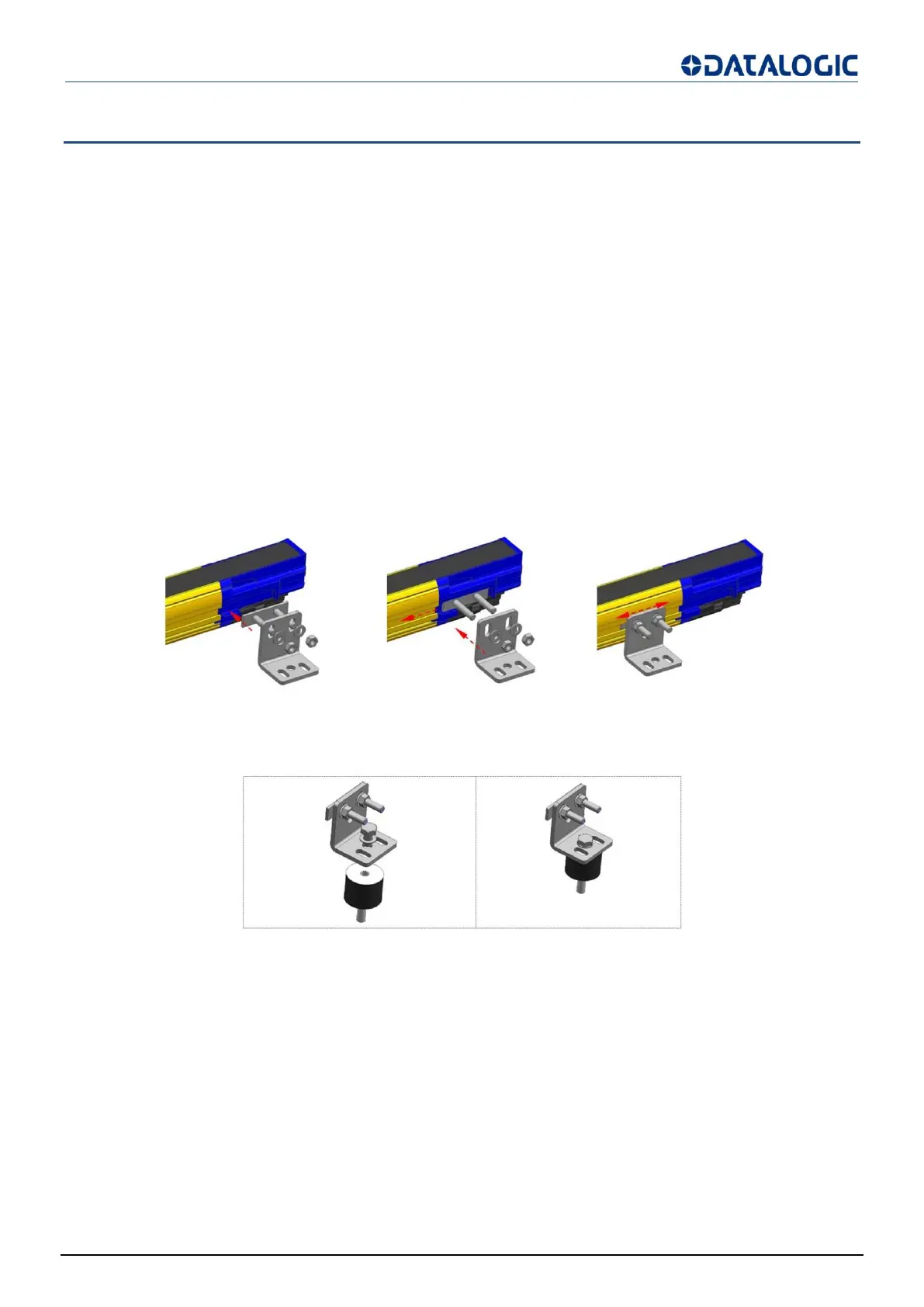
Outfit angled fixing brackets kit, for units mounting, must be used as described below (Fig 21 - page 26).
Adjustable supports for adjusting unit inclinations around the axes are available on request (see
cfr.ACCESSORIES page 65).
To mount the angled fixing brackets kit, place the threaded pins metallic insert into the dedicated side seat of the
terminator cap side light curtain closing cap; slide the insert towards the metallic drawn profile groove.
Fix the bracket against the profile by tightening the M5 hexagonal nuts. It’s possible to slide the bracket group
along their dedicated rail and fix it once again just working on the above mentioned nuts.
Fig 21 - Fixed brackets mounting procedure
In case of applications with particularly strong vibrations, vibration dampers, together with mounting brackets, are
recommended to reduce the impact of the vibrations.
Fig 22 - Anti-vibration dampers