4 ELECTRICAL CONNECTIONS
4.1 PIN-OUT AND CONFIGURATION PIN CONNECTION
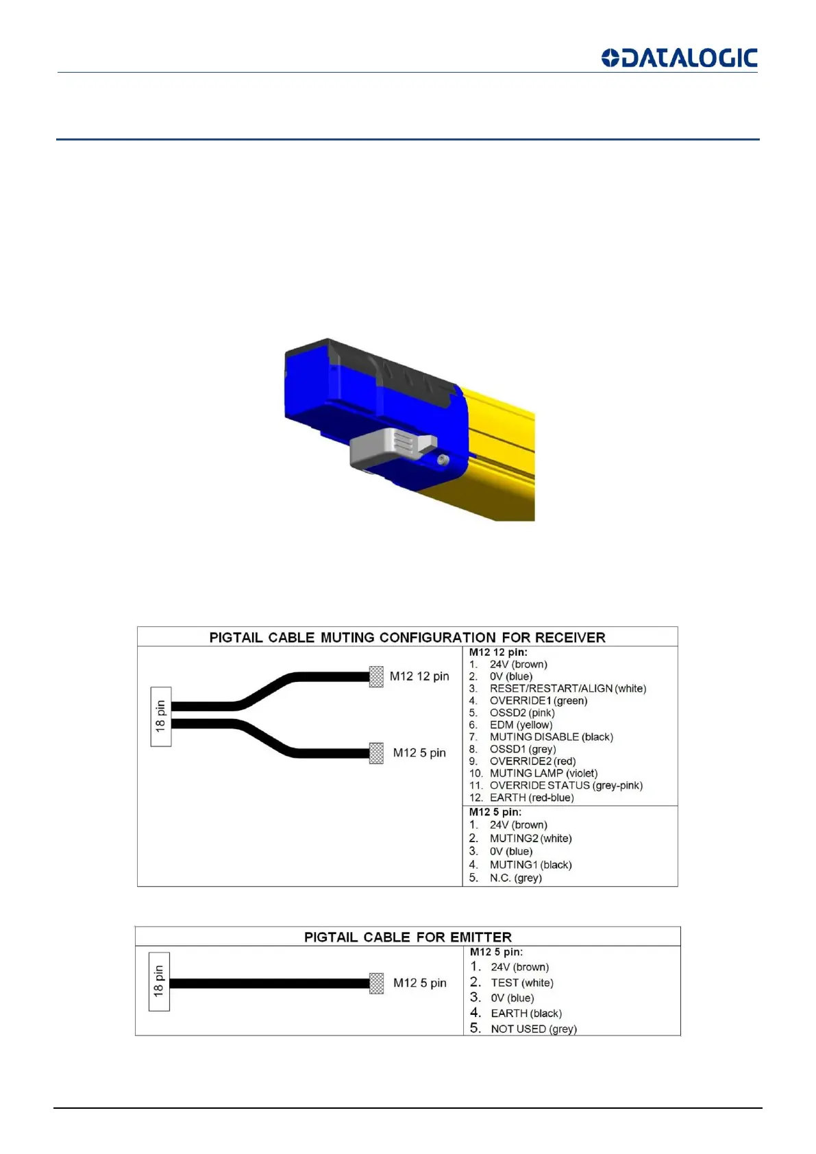
All electrical connections to the emitting and receiving units are made through some particular cables; these cables
are composed of a rectangular 18 pin connector on light curtain side and M12 male connector(s) on the other side.
The Muting cable allows to have on the receiving unit one M12 12-pole connector and one M12 5-pole connector.
The Blanking cable allows to have on the receiving unit one M12 12-pole connector.
The emitting unit has one M12 5-pole connector (both in Muting and Blanking mode).
The cables have to be connected on the bottom side of the light curtains (leds and push button side) by removing
the white cap that is present.
Take care that the terminator cap (CVL-5196, see cfr.INCLUDED ACCESSORIES page 63) is connected on the
top side of the light curtains.
If this connection misses, Master and Slave units go in critical Communication failure.
Fig 25 - Pigtail cable - Muting configuration for receiver RX (CS-R1-75-B-002)
Fig 26 - Pigtail cable - configuration for emitter TX (CS-G1-50-B-002)
 Loading...