EasyManua.ls Logo

Datalogic SG4-30-015-OO-E - 4 Electrical Connections; Pin-Out and Configuration Pin Connection; MODELS SG4-XX-XXX-OO-X

Datalogic SG4-30-015-OO-E
74 pages
To Next Page IconTo Next Page
To Previous Page IconTo Previous Page
Loading...
SG4 BASE
28/74
4 ELECTRICAL CONNECTIONS
4.1 PIN-OUT AND CONFIGURATION PIN CONNECTION
4.1.1 MODELS SG4-xx-xxx-OO-X
All electrical connections to the emitting and receiving units are made through a male M12 connector, located on
the lower part of the two units.
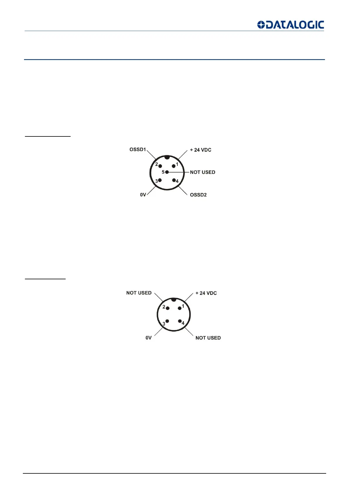
For receiver a M12 5-poles connector is used, while for emitter a M12 4-poles connector is used.
RECEIVER (RX):
Fig 25 - Receiver
1 =
brown
= +24 VDC
2 =
white
= OSSD1
3 =
blue
= 0 V
4 =
black
= OSSD2
5 =
grey
= NOT USED
EMITTER (TX):
Fig 26 - Emitter
1 =
brown
= +24 VDC
2 =
white
= NOT USED
3 =
blue
= 0 V
4 =
black
= NOT USED

Table of Contents

Related product manuals