Appendix C – Paper Menu Setup 74
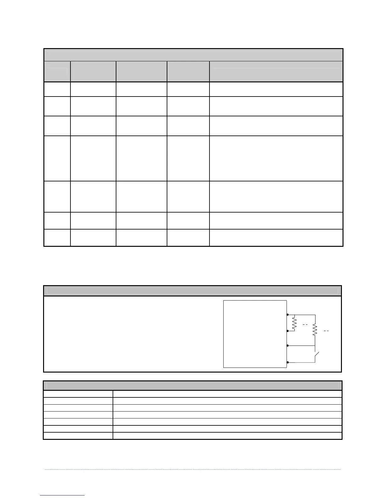
Each GPIO pin function is detailed in the table below:
GPIO Port Connections and Functions
Pin #
Signal
Name
Signal
State
Signal
Direction
[1]
Signal Description
[2]
1 Vcc +5 VDC Output Printer: Max +5 VDC, 100mA
2 Printer Fault Low Output
Goes low upon printer detection of a fault
condition. Max +5 VDC, 100mA
3 Spare Reserved Input
Must be pulled high with 1k Ohm resistor
(see sample SOP circuit, below).
4
Start of Print
(SOP)
Programmable Input
When active, will begin print. Recommend
only setting this signal to ACTIVE LOW. When
ready to print a label, the applicator should
hold this signal low for at least 50ms – or
until EOP goes not active. See sample SOP
circuit, below. Max +3.27 VDC, +/-5mA
5
End of Print
(EOP)
Programmable Output
Signifies the end of the print process. Can be
monitored to initiate next Start of Print
sequence. Minimum signal time 30ms. Max
+5 VDC, 100mA
6 & 8 Signal Ground Ground N/A Ground
7 +24 VDC 500mA Output Printer: Max +24 VDC, 500mA
[1]
Given relative to the printer.
[2]
The operation of this multi-function port is configuration dependent. For GPIO operation, disable all optional
functions not used (i.e., Present Sensor and Cutter) and set GPIO to “YES” (or on display-equipped models set
GPIO Device to “APPLICATOR”). Use the Configuration Set command (<STX>Kc), or program the selections on
non-display models via the “Printer Setup Menu List” or on display-equipped models via the “Menu System.”
Sample SOP Circuit
Pin 3 should be pulled to +5VDC. In addition, connections
for the external Start of Print control can either be directly
made to Pin 4 of the Option Port (or Main PCB connector)
using a TTL-level input, or via an interface circuit (similar
to the one shown). For more information, see the table
below.
1
8
Vcc
Gnd
GPIO Connector Pin Number
3Spare
4SOP
1K
O
1K
O
GPIO Port Specifications
V
in
max 5.5 VDC maximum input into any pin
V
IH
3.8 VDC minimum (high level input voltage)
V
IL
0.36 VDC maximum (low level input voltage)
I
OH
-8 mA typical, - 25 mA maximum (high level output current)
I
OL
8 mA typical 25 mA maximum (low level output current)
V
OH
I
OH
=
-8
mA, minimum 3.8 VDC
V
OL
I
OL
=
8
mA, maximum .44 VDC