19
5. Continue setting the next sequential repeater ID for each repeater in the chain.
Verifying Communication with a Transmitter and
Repeaters
Always start verifying communication at the beginning of the chain, which is repeater A.
Once communication between repeater A and a transmitting station is established, move
to the next repeater in the chain and make sure it can receive packets from repeater A.
Repeat this process until you have reached the end of the chain closest to the receiver.
1. Place the first repeater in an area where it is likely to receive the transmitting station
signal.
The repeater that received the default ID of Repeater A is the only repeater in the
network that must be configured with that transmitting station’s Transmitter ID.
2. Turn the Transmitter ID for the transmitting station ON on the Transmitter ID switch.
3. Put the repeater into Test Mode by turning on the repeater DIP Switch #4. The repeater
goes through the following process:
• It looks for a transmitting station signal for ten minutes, with the "STAT" LED
flashing red when it detects any signal (not necessarily associated with a station).
• It flashes yellow if it has found some transmitting stations but not all (if more than
one transmitting station has been selected), and then;
• It flashes green when all transmitting stations are found. For each transmitting
station found, the "TX" LED flashes immediately after the "STAT" LED, indicating
that it is transmitting the station ID(s).
Note: See “Maintenance and Troubleshooting” if you do not see the described LED pattern after ten minutes.
Wait for repeater A to fully acquire a signal from the transmitting station before proceeding to the next
repeater in the chain, otherwise the second repeater will not be able to acquire repeater A.
1
A
B
C
Repeater
1 1
1
Repeater
11
Repeater
1
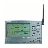
Vantage Pro2
Console/Receiver
A
B C
C
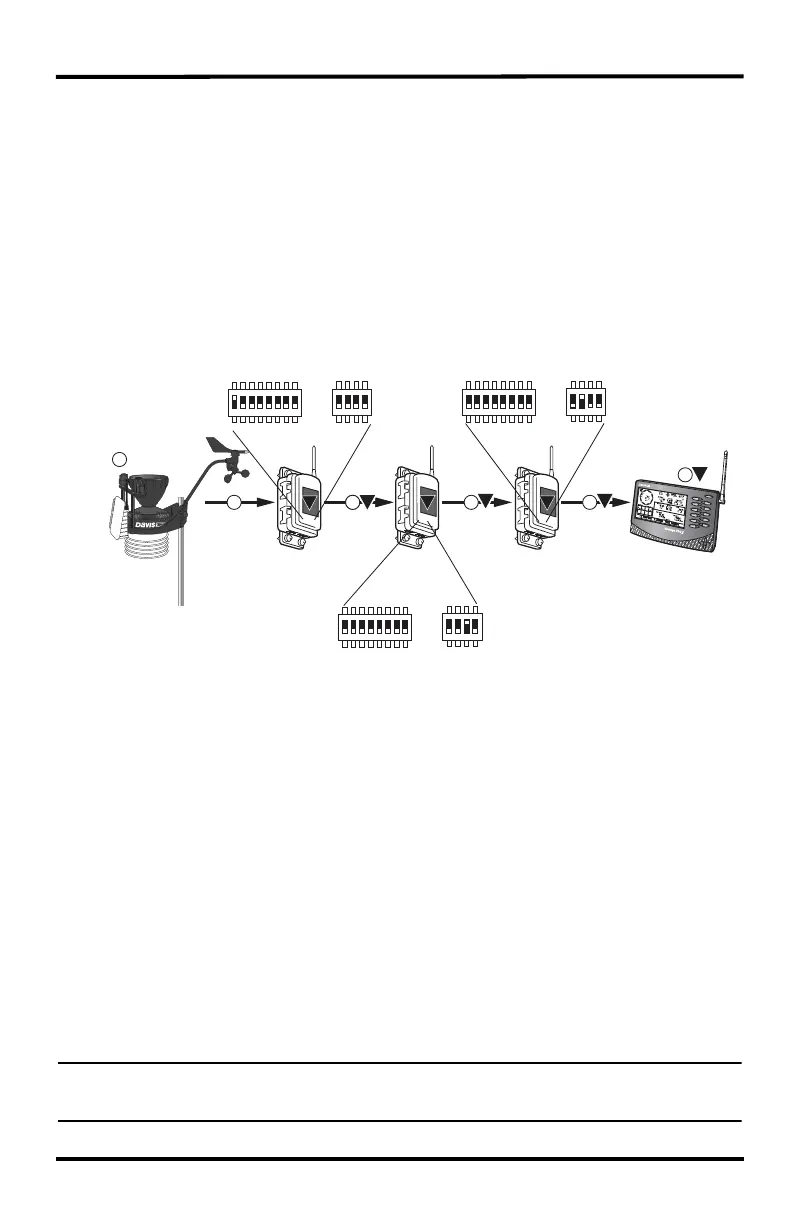
Transmitter DIP
Switch with ID 1 ON
Repeater DIP
Switch set to ID A
Transmitter DIP Switch
All IDs OFF
Repeater DIP
Switch set to ID B
Transmitter DIP Switch
All IDs OFF
Repeater DIP
Switch set to ID C
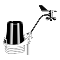
Vantage Pro2
ISS
Use the following diagram for an example of transmitter and repeater DIP switch settings for
each repeater in a daisy chain
 Loading...