The DEIF ASC 150 Storage is an advanced controller designed for energy storage systems (ESS), offering comprehensive management and control functionalities for various applications, including grid-forming, grid-following, and parallel operations with mains or gensets. This operator's manual provides detailed information on its operation, technical specifications, and maintenance.
Function Description
The ASC 150 Storage controller serves as the central brain for energy storage systems, enabling them to act as an energy source in island operation (V/f mode or off-grid) or to work in conjunction with other non-grid-forming sources like solar and wind. In grid-following mode (parallel or P/Q mode), the battery is connected to a grid-forming source, such as a mains or genset, to achieve optimal genset load or maintain a minimum genset load. The controller supports droop mode (VSG - virtual synchronous generator) for island operations and parallel operations (grid-following).
The system manages energy sources and power flows, allowing the ESS to contribute to the overall energy management system. It can operate in AUTO mode, SEMI-AUTO mode, or LOCAL mode, providing flexibility in control. In AUTO mode, the system closes the ESS breaker if there is energy storage charging or discharging, or if the plant has a start signal. The controller also supports automatic mains failure (AMF) detection and response, ensuring continuous power supply.
Key functionalities include:
- Grid-forming and Grid-following: The controller supports both modes, allowing the battery to act as an independent energy source or to work in parallel with other grid sources.
- Energy Source or Power Source: The ASC 150 Storage controller prioritises battery power over genset power. It can reduce genset load to minimum (P DG minimum) and works as a power source with spinning reserve functionality.
- Charging and Discharging: The ESS can recharge from gensets or mains. The controller uses parameters like 17025 (Mains charge mode) and 17033 (DG Charge mode) to configure the charging source. SOC-based charging only and SOC + plant assist charging options are available.
- AC- or DC-coupled connections: The system supports both AC-coupled connections (with an ASC Solar and ASC Storage controlling the ESS) and DC-coupled connections (with a separate charger or PV charging the battery directly).
- Mimic Function: The controller features an LED mimic display that shows the operational status of the ESS. Red LEDs indicate an energy storage system (ESS) stop, while green LEDs indicate normal operation. Specific symbols show breaker position, breaker close failure, synchronising status, and de-loading.
- Running Modes: The controller has four running modes: AUTO (remote), SEMI-AUTO (local), and two additional modes for manual operation. In AUTO mode, the controller operates automatically, and the operator cannot start sequences manually. In SEMI-AUTO mode, the operator must start all sequences.
- Display Settings: Various display settings can be adjusted, including backlight dimmer, green and red LED dimmers, contrast level, sleep mode timer, and alarm jump.
- Utility Software: The application supervision function in the utility software allows monitoring of power production. It also provides tools for data monitoring and counters, including power meter monitoring, electrical data monitoring, ESS data, and USW counters.
- Trending: The trending function in the utility software enables real-time operation monitoring, with the ability to save trending data to a .trend file and view historical trends.
- Alarm Handling and Log List: The controller displays alarms on the display unit, and the alarm list can be accessed to view active and acknowledged alarms. The log list stores events and alarms, showing up to 500 events and 100 alarms.
Important Technical Specifications
While specific numerical values for current, voltage, and power are not explicitly detailed in the provided text, the manual highlights several key operational ranges and parameters:
- Fixed Power Set Point: The ESS can be configured with a fixed power set point for PV fixed power, ranging from -20000 to 2000 kW, with a default of 500 kW.
- Mains Power Export: Parameters for mains power export (Day and Night) range from -20000 to 20000 kW, with default values of 750 kW (Day) and 1000 kW (Night).
- MPE/PS Scale: The Mains Power Export/Peak Shaving scale can be set to 1kW:1kW, 1kW:10kW, 1kW:100kW, or 1kW:1000kW.
- Daytime Period: Start hours for daytime periods range from 0 to 23, and start/stop minutes from 0 to 59. Default start hour is 8, and default stop hour is 16.
- Display Resolution: The display has a resolution of 240 x 128 pixels, with a viewing area of 48.50 x 51.40 mm, and can show six lines with 25 characters.
- Display Views: The controller has 20 display views, with 18 pre-configured views, and additional views can be configured using the utility software.
- SOC Conditions: The State of Charge (SOC) conditions determine whether the ESS can be a power source or if discharging is allowed. Thresholds 1 and 2 are critical for these operations.
Usage Features
The ASC 150 Storage is designed for user-friendly operation with a clear interface and intuitive navigation.
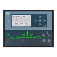
- Display, Buttons, and LEDs: The controller features a display, navigation buttons (up, down, left, right, OK), and various LEDs to indicate status.
- Power (1): Green indicates the controller power is ON; OFF indicates it's OFF.
- Display Screen (2): Shows information with a resolution of 240 x 128 pixels.
- Navigation (3): Moves the selector up, down, left, and right on the screen.
- OK (4): Enters the Menu system or confirms selection.
- Back (5): Returns to the previous page.
- AUTO Mode (6): Automatically starts and stops the storage system.
- Silence Horn (7): Turns off an alarm horn.
- Shortcut Menu (8): Accesses jump menu, mode selection, test, lamp test, and storage.
- SEMI-AUTO Mode (9): The operator can start or stop, open and close the storage breaker.
- Mains Symbol (10): Green indicates mains/busbar voltage and frequency are OK; Red indicates mains/busbar voltage failure.
- Close Breaker (11): Pushes to close the breaker.
- Open Breaker (12): Pushes to open the breaker.
- Breaker Symbols (13): Green indicates the breaker is closed; Green flashing indicates synchronising or de-loading; Red indicates breaker failure.
- Power Converter (14): Green indicates power converter voltage and frequency are OK; Green flashing indicates power converter voltage and frequency are OK, but the V&Hz OK timer is still running; Red indicates the controller cannot close the breaker or power converter voltage is too low to measure.
- Battery Management System (15): Green indicates storage system available feedback; Green flashing indicates the storage system is getting ready; Red indicates the storage system is not running or no availability feedback.
- Stop (16): Stops the power converter if SEMI-AUTO is selected.
- Start (17): Starts the power converter if SEMI-AUTO is selected.
- Load Symbol (18): Green indicates power management application; Green indicates supply voltage and frequency are OK; Red indicates supply voltage/frequency failure.
- Menu Structure: The controller has two menu systems: the view menu (shows operating status and values) and the settings menu (allows configuration of parameters). Access to these menus can be password-protected.
- Jump to Parameter Function: This feature allows direct navigation to specific parameters by entering their menu number.
- View Menu: Provides an overview of operating status, values, and state of charge (SOC) information.
- Display Views: Users can configure and select different display views to monitor various parameters.
- Service View: Allows users to check the status of the controller and configure communication settings.
- General Shortcuts: Configurable shortcuts provide quick access to frequently used functions.
Maintenance Features
The manual provides information relevant to maintenance, primarily through its diagnostic and logging capabilities.
- Alarm Handling: The alarm list helps identify and troubleshoot issues by displaying active and acknowledged alarms. This is crucial for prompt maintenance and fault resolution.
- Log List: The event log and alarm log store historical data, which can be invaluable for diagnosing intermittent problems, tracking system performance over time, and understanding the sequence of events leading to a fault.
- Utility Software for Data Monitoring: The application supervision and trending functions in the utility software allow for continuous monitoring of system performance, which can help in predictive maintenance by identifying potential issues before they lead to failures.
- Communication Troubleshooting: The manual details communication protocols (Modbus Master RTU, TCP/IP) and provides information on how to troubleshoot communication failures between the ASC 150 Storage controller and the battery management system (BMS) or battery control unit (BCU). This ensures that all components of the ESS are communicating effectively.
- Warnings and Safety: The manual includes symbols for hazard statements (DANGER, WARNING, CAUTION, NOTICE) to ensure operators are aware of potential risks and follow safety guidelines during installation, operation, and maintenance. This includes warnings about dangerous situations, potentially dangerous situations, low-level risks, and important notices.
- Warranty: The controller is delivered pre-programmed from the factory with default settings. Any modifications by unauthorised personnel will void the warranty. This emphasizes the importance of professional installation and maintenance.
- Software Version: The document specifies that the information is based on the AGC 150 software version 1.14.0, which is important for ensuring compatibility and understanding specific features related to that software release.
In summary, the DEIF ASC 150 Storage controller is a robust and versatile solution for managing energy storage systems, offering advanced control, extensive monitoring, and diagnostic tools to ensure reliable and efficient operation.