Installing System Board Options 7-9
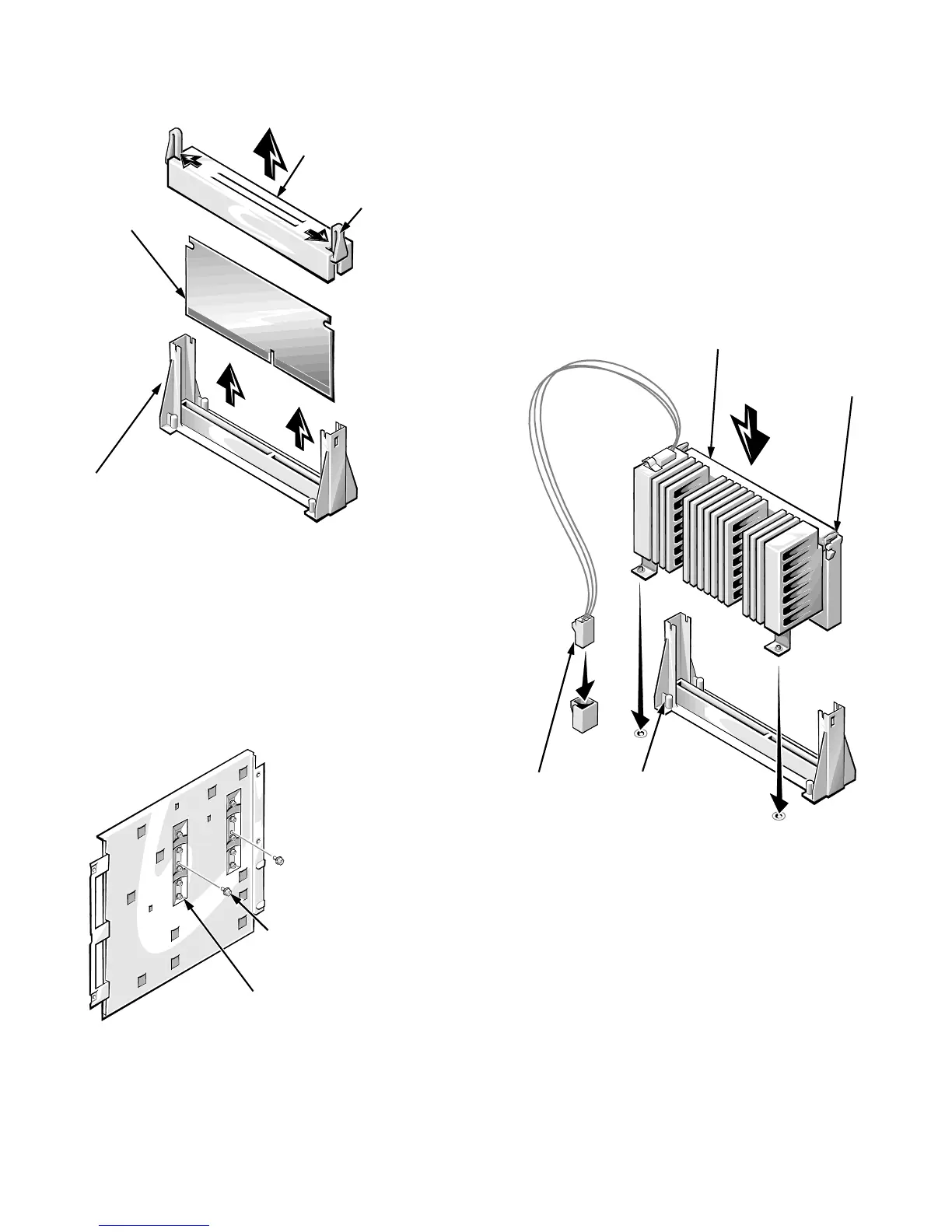
Figure 7-8. Terminator Card
4. If you are upgrading an existing microprocessor,
remove the microprocessor module:
a. Carefully stand the system board assembly on
one edge. Using a
1/4
-inch nut driver, remove
the two hexagonal screws securing the micro-
processor module to the system board (See
Figure 7-9).
Figure 7-9. Microprocessor Module
Retention Screws
b. Disconnect the microprocessor temperature-
sensor cable from the system board and the
microprocessor module.
c. Press inwards on the microprocessor-module
retention latches (see Figure 7-10) until they
snap into a retracted position.
d. Lift the microprocessor module straight up and
out of the microprocessor retention bracket on
the system board.
Figure 7-10. Installing a Microprocessor
Module
5. Install the new microprocessor module.
Align the microprocessor module with the micro-
processor retention bracket on the system board, as
shown in Figure 7-10. Lower the microprocessor
module into the microprocessor retention bracket,
and press firmly on the top of the module until the
microprocessor module is fully seated and the reten-
tion latches snap into position.
terminator-card
retention bracket cover
terminator
card
microprocessor
retention bracket
tabs (2)
primary microprocessor-
module retention screws (2)
secondary microprocessor-
module retention screws (2)
microprocessor module
microprocessor
retention bracket
microprocessor-module
retention latches (2)
temperature
sensor cable