Steps
1. Remove the two screws (M2.5x5) that secure the left-display hinge to the palm-rest and keyboard assembly.
2. Peel the tape that secures the camera-cable connector latch to the system board.
3. Lift the latch and disconnect the camera cable from the system board.
4. Peel the tapes that secure the power-adapter port cable to the system board.
5. Move the power-adapter port cable off the display-cable connector on the system board.
6. Peel the tape that secures the display-cable connector latch to the system board.
7. Lift the latch and disconnect the display-cable connector from the system board.
8. Remove the two screws (M2.5x5) that secure the power-adapter port-bracket to the palm-rest and keyboard assembly.
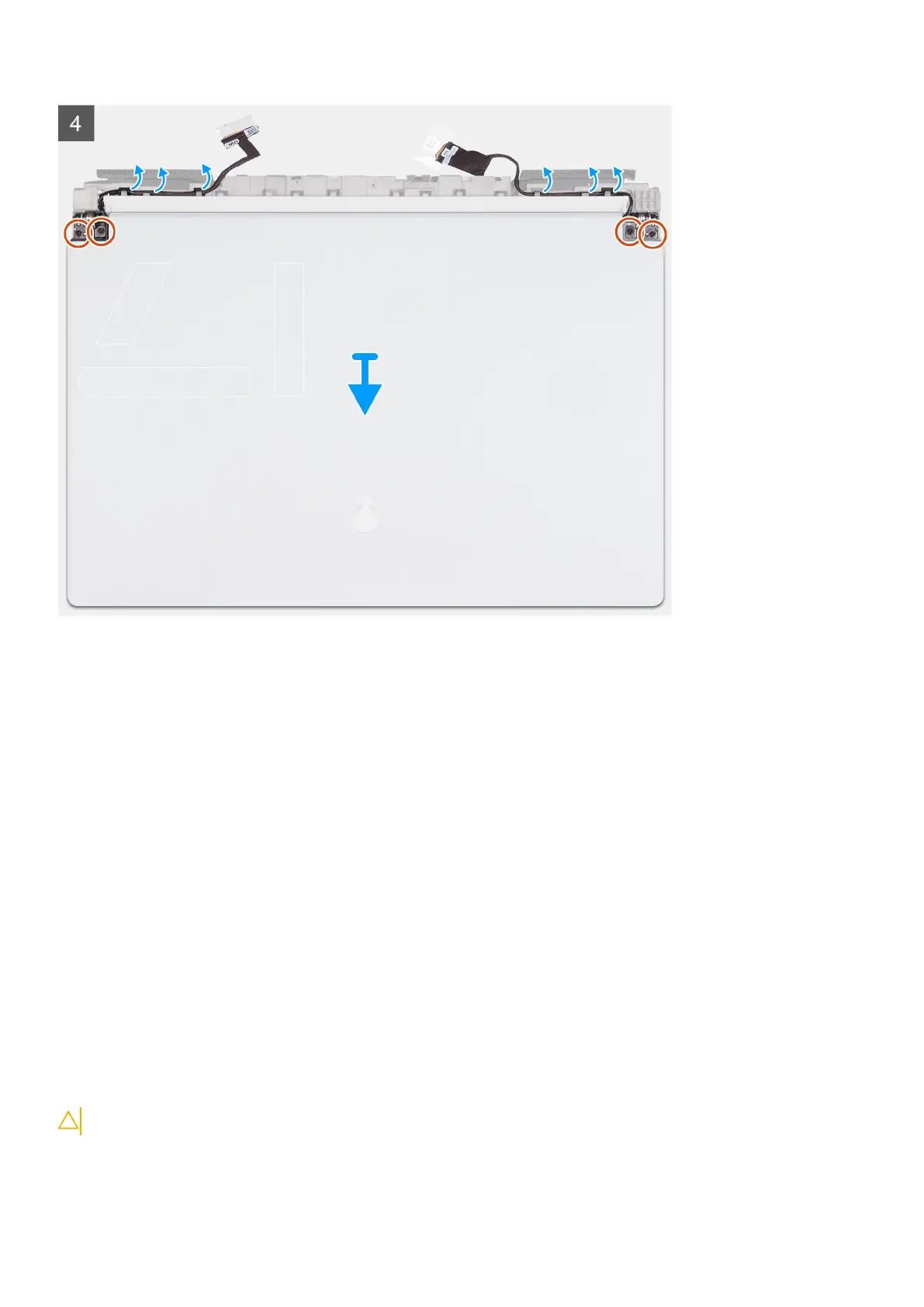
9. Turn the computer over
10. Remove the display cable from the routing guide on the palm-rest and keyboard assembly.
11. Remove the Tobii-eye cable from the routing guide on the palm-rest and keyboard assembly.
12. Remove the four screws (M2.5x5) that secure the display assembly to the palm-rest and keyboard assembly.
13. Lift the display assembly off the palm-rest and keyboard assembly.
Installing the display assembly
Prerequisites
If you are replacing a component, remove the existing component before performing the installation process.
About this task
CAUTION: Place the display assembly on a clean and flat surface to avoid damaging the display assembly.
The following image(s) indicate the location of the display assembly and provides a visual representation of the installation
procedure.
44
Removing and installing components