Steps
1. Turn the system-board assembly over.
2. Install the fan and heat-sink assembly.
3. Using the two alignment posts shown in the image, place the system-board assembly on the palm-rest and keyboard
assembly.
NOTE:
When placing the system-board assembly on the palm-rest and keyboard assembly ensure that the power button
cable is placed on top of the system board. Overlooking the power-button cable connection to the system board will
result in no-power failure after service.
4. Align the screw holes on the system-board assembly to the screw holes on the palm-rest and keyboard assembly.
5. Replace the four screws (M2x3) that secure the system-board and heat-sink assembly to the palm-rest and keyboard
assembly.
6. Replace the screw (M2x4) that secures the system board to the palm-rest and keyboard assembly.
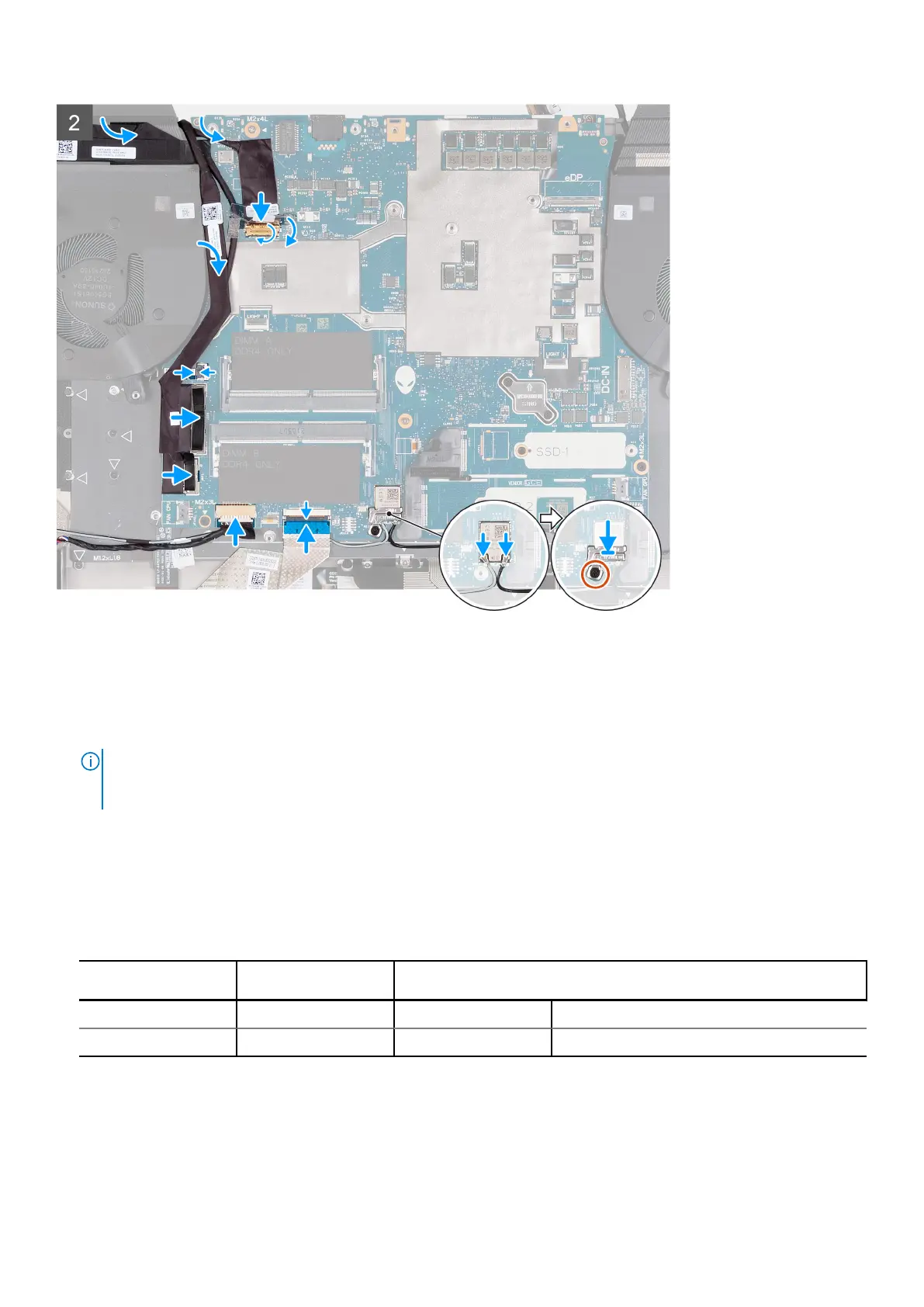
7. Connect the antenna cables to the wireless-card on the system board.
Table 2. Antenna-cable color scheme
Connectors on the
wireless card
Antenna-cable color Silkscreen marking
Main White MAIN △ (white triangle)
Auxiliary Black AUX ▲ (black triangle)
8. Place the wireless card bracket over the wireless card on the system board.
9. Replace the screw (M2x3) that secures the wireless-card bracket to the system board.
10. Connect the keyboard-controller board cable to the system board and close the latch.
11. Connect the speakers cable to the system board.
12. Connect the power-button cable to the system board and close the latch.
Removing and installing components
57