9. Remove the left fan.
10. Remove the right fan.
11. Remove the heat pipe.
12. Remove the display assembly.
13. Remove the touchpad.
14. Remove the keyboard-controller board.
15. Remove the system board.
NOTE: The system board can be removed and installed along with the heat sink, memory and solid-state drives. This
simplifies the removal and installation procedure and avoids breaking the thermal bond between the system board and
heat sink.
16. Remove the power button.
17. Remove the I/O board.
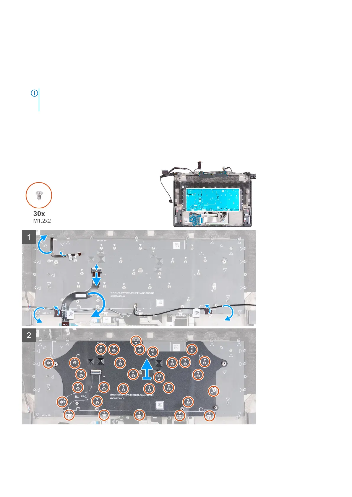
About this task
The following image(s) indicate the location of the keyboard bracket and provides a visual representation of the removal
procedure.
Steps
1. Peel and lift the power-button cable off the palm-rest and keyboard assembly.
Removing and installing components
65