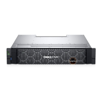
Procedure A, Task 2: EMC Customer Engineer (VMAX 250F)
Before you begin
Before connecting power to the system, make sure that the power for both zone A
and zone B are turned OFF. This task is performed by the EMC Customer Engineer.
Figure 41 PDP power switches for Zone A and B
Rear view
Example shown:
2 V-Bricks
PDP
1010
A
B
1010
A
B
ON
I
OFF
O
ON
I
OFF
O
ON
I
OFF
O
ON
I
OFF
O
ON
I
OFF
O
ON
I
OFF
O
PDU
40U rack
PDP
PDU
Power zone A
(right, gray)
Power zone B
(left, black)
(Power zone B)
(Power zone B)
(Power zone A)
(Power zone A)
ON
|
OFF
Zone A
Zone A
power switch
ON
|
OFF
Zone B
Zone B
power switch
Procedure
1. Confirm that the customer-supplied power cables are labeled and that each
label contains the relevant customer-supplied PDU and circuit breaker numbers.
If power cables are not equipped with labels, alert the customer.
2. Compare the numbers on the customer-supplied power cables for each EMC
bay to verify that power zone A and power zone B are powered by a different
customer-supplied PDU.
3. Do the following to connect power zone A and power zone B in each bay. You
must use the 15ft extension cords provided by EMC. To ensure serviceability,
make sure there is 2ft (61cm) of cable slack directly under the bay floor-egress.
See VMAX 250F customer AC power feed cabling on page 73 for more details.
l
For both single-phase and three-phase, connect customer-supplied PDU
power cables to the EMC bay by connecting to the bay's AC input cables for
power zone A and power zone B as shown below:
Best Practices for AC Power Connections
120 Site Planning Guide VMAX 250F, VMAX 450F, VMAX 850F, VMAX 950F with HYPERMAX OS
 Loading...
