additional pedestal mounts relative to a cutout should be in accordance with the
tile manufacturer’s recommendations.
l
Take care when positioning the bays to make sure that a caster is not moved into a
cutout. Cutting tiles per specifications ensures the proper caster placement.
l
Use or create no more than one floor tile cutout that is no more than 8 in. (20 cm)
wide by 6 in. (15 cm) deep in each 24 x 24 in. (61 x 61 cm) floor tile.
l
Ensure that the weight of any other objects in the data center does not
compromise the structural integrity of the raised floor or the subfloor (nonraised
floor) of the data center.
Physical space and weight
The following table provides the physical space, maximum weights, and clearance for
service.
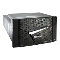
VMAX 250F
Table 17 Space and weight requirements, VMAX 250F
Bay
configurations
a
Height
(in/cm)
b
Width
(in/cm)
Depth
c
(in/cm)
Weight
(max lbs/kg)
1 system, 1 V-Brick 75/190 24/61 42 in (106.7 cm) 570/258
1 system, 2 V-Bricks,
or
2 systems, 1 V-Brick
each
75/190 24/61 42 in (106.7 cm) 850/385
2 systems, 2 V-
Bricks in one system,
1 V-Brick in other
75/190 24/61 42 in (106.7 cm) 1130/513
2 systems, 2 V-
Bricks each system
75/190 24/61 42 in (106.7 cm) 1410/640
a.
Clearance for service/airflow is the front at 42 in (106.7 cm) front and the rear at 30 in
(76.2 cm).
b.
An additional 18 in (45.7 cm) is recommended for ceiling/top clearance.
c.
Includes rear door.
VMAX 450F, VMAX 850F, VMAX 950F
Table 18
Space and weight requirements, VMAX 450F, VMAX 850F, VMAX 950F
Bay
configurations
a
Height
b
(in/cm)
Width
c
(in/cm)
Depth
d
(in/cm)
Weight
(max lbs/kg)
System bay 75/190 24/61 47/119 1860/844
a.
Clearance for service/airflow is the front at 42 in (106.7 cm) front and the rear at 30 in
(76.2 cm).
b.
An additional 18 in (45.7 cm) is recommended for ceiling/top clearance.
c.
Measurement includes .25 in. (0.6 cm) gap between bays.
d.
Includes front and rear doors.
Physical weight and space
Physical space and weight 41

 Loading...


