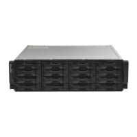
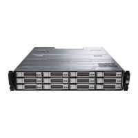
3 Maintaining Drives
This section describes the drives used in the PS-M4110 blade storage array. It includes information about how to
identify failed drives, how to interpret drive LEDs, array behavior when a drive fails, drive handling
requirements, and how to install and remove drives.
About Drives
The PS-M4110 blade storage array drives are located within the array drawer. They connect to the array, and to
the M1000e, through a bottomplane in the drawer.
The array drives are hot-swappable. You can replace a failed drive while the array remains running.
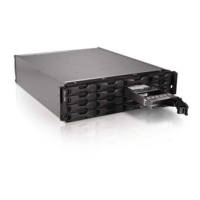
Drives are supplied in a carrier that is keyed to fit into specific array models and cannot be installed in other
Dell arrays or arrays that are not supplied by Dell Inc.
All the procedures for replacing, handling, and identifying a failed drive are the same for a PS-M4110 as they
are for any other Dell EqualLogicPS Series array.
About Mixed-Drive Arrays (Rotational and Solid State)
The PS-M4110 can support a combination of five solid state drives (SSDs) and 9 rotational drives (HDs) in the
array. The proportion of SSDs to HDs cannot be changed.
The SSDs occupy slots 0-4 by default, but may be used in any drive slot.
Identifying Failed Drives
The drives are numbered 0 through 13 from the front of the array to back.
A drive failure is indicated by:
• LEDs on the drive. See Interpreting Drive LEDs on page 28.
• LEDs on the front panel of the array. See Chapter , Interpreting Control Module LEDs on page 37.
• A message on the console, in the event log, or in the Group Manager Alarms panel.
27
 Loading...